Toyota 4Runner: Disassembly
DISASSEMBLY
PROCEDURE
1. REMOVE COOLER BRACKET
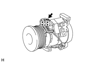
(a) Detach the clamp.
(b) Remove the screw and cooler bracket.
2. REMOVE MAGNET CLUTCH ASSEMBLY
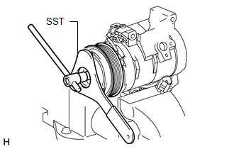
(a) Clamp the cooler compressor in a vise.
(b) Using SST, hold the magnet clutch hub.
SST: 07112-76060
(c) Remove the bolt, magnet clutch hub and magnet clutch washer(s).
HINT:
There is no set number of magnet clutch washers since they are used for adjusting.
|
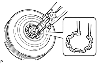
(d) Using a snap ring expander, remove the snap ring and magnet clutch rotor. NOTICE: Do not damage the seal cover of the bearing when removing the snap ring. |
|
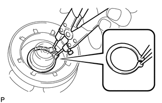
(e) Disconnect the connector.
|
(f) Using a snap ring expander, remove the snap ring and magnet clutch stator. |
|
 Components
COMPONENTS
ILLUSTRATION
ILLUSTRATION
...
 Inspection
INSPECTION
PROCEDURE
1. INSPECT MAGNET CLUTCH ASSEMBLY
(a) Check the magnet clutch operation.
(1) Confirm that the magnet clutch hub and magnet clutch rotor lock when the
positive (+) lead of ...
Other materials about Toyota 4Runner:
Side Step
Components
COMPONENTS
ILLUSTRATION
ILLUSTRATION
Disassembly
DISASSEMBLY
CAUTION / NOTICE / HINT
HINT:
Use the same procedure for the RH and LH sides.
The procedure listed below is for the LH side.
PROCEDURE
1. REMOVE SIDE ST ...
Pump Motor Relay (C1253)
DESCRIPTION
The motor relay (semiconductor relay) is built into the master cylinder solenoid
and drives the pump motor based on a signal from the skid control ECU.
DTC Code
DTC Detection Condition
Trouble Area
...
0.012