Toyota 4Runner: Inspection
INSPECTION
PROCEDURE
1. INSPECT MAGNET CLUTCH ASSEMBLY
(a) Check the magnet clutch operation.
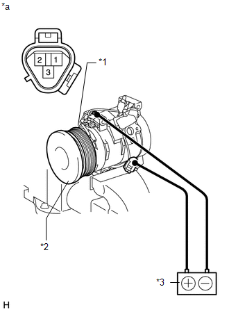
(1) Confirm that the magnet clutch hub and magnet clutch rotor lock when the positive (+) lead of the battery is connected to terminal 3 of the magnet clutch, and the negative (-) lead is connected to the ground wire.
If the operation is not as specified, replace the magnet clutch assembly.
Text in Illustration|
*1 |
Magnet Clutch Rotor |
|
*2 |
Magnet Clutch Hub |
|
*3 |
Battery |
|
*a |
Component without harness connected (Magnet Clutch Assembly) |
(b) Measure the resistance between terminals 1 and 2.
Standard resistance:
65 to 125 Ω at 20°C (68°F)
If the result is not as specified, replace the cooler compressor assembly.
 Disassembly
DISASSEMBLY
PROCEDURE
1. REMOVE COOLER BRACKET
(a) Detach the clamp.
(b) Remove the screw and cooler bracket.
2. REMOVE MAGNET CLUTCH ASSEMBLY
(a) Clamp the cooler compressor in a vise.
(b) ...
 Removal
REMOVAL
PROCEDURE
1. REMOVE GENERATOR ASSEMBLY
(a) Remove the generator assembly (See page
).
2. RECOVER REFRIGERANT FROM REFRIGERATION SYSTEM
3. DISCONNECT DISCHARGE HOSE SUB-ASSEMBLY
...
Other materials about Toyota 4Runner:
Engine (ignition) switch (vehicles with a smart key system)
Performing the following operations when carrying the electronic key on
your person starts the engine or changes “ENGINE START STOP” switch modes.
Starting the engine
Check that the parking brake is
set.
Check that the shift lever is
set in P.
...
All Doors LOCK/UNLOCK Functions do not Operate Via Master Switch, Driver Side
Door Key Cylinder
DESCRIPTION
The main body ECU (multiplex network body ECU) receives switch signals from the
multiplex network master switch, and key-linked switch signals from the front door
lock. The main body ECU (multiplex network body ECU) activates the door lock mot ...
0.0087