Toyota 4Runner: ECU Power Source Circuit
DESCRIPTION
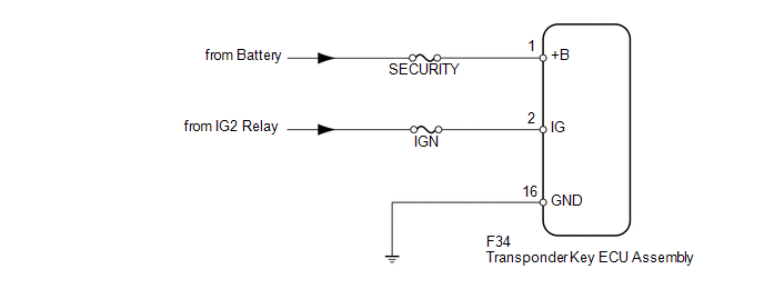
This circuit provides power to operate the transponder key ECU assembly.
WIRING DIAGRAM
CAUTION / NOTICE / HINT
NOTICE:
Inspect the fuses for circuits related to this system before performing the following inspection procedure.
PROCEDURE
|
1. |
CHECK HARNESS AND CONNECTOR (TRANSPONDER KEY ECU - BATTERY AND BODY GROUND) |
|
(a) Disconnect the F34 ECU connector. |
|
(b) Measure the voltage according to the value(s) in the table below.
Standard Voltage:
|
Tester Connection |
Switch Condition |
Specified Condition |
|---|---|---|
|
F34-1 (+B) - Body ground |
Always |
11 to 14 V |
|
F34-2 (IG) - Body ground |
Ignition switch off |
Below 1 V |
|
Ignition switch ON |
11 to 14 V |
(c) Measure the resistance according to the value(s) in the table below.
Standard Resistance:
|
Tester Connection |
Condition |
Specified Condition |
|---|---|---|
|
F34-16 (GND) - Body ground |
Always |
Below 1 Ω |
|
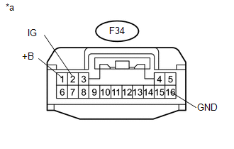
*a |
Front view of wire harness connector (to Transponder Key ECU Assembly) |
| OK | .gif) |
PROCEED TO NEXT SUSPECTED AREA SHOWN IN PROBLEM SYMPTOMS TABLE |
| NG | |
REPAIR OR REPLACE HARNESS OR CONNECTOR |
 Security Indicator Light Circuit
DESCRIPTION
When the engine immobiliser system is set, the security indicator light
blinks continuously, but does not illuminate if the engine immobiliser system
is not set.
WIR ...
 Id Code Box
Components
COMPONENTS
ILLUSTRATION
Installation
INSTALLATION
PROCEDURE
1. INSTALL ID CODE BOX
(a) Attach the 2 claws and move the ID code box in the direction of the
arrow. ...
Other materials about Toyota 4Runner:
Removal
REMOVAL
CAUTION / NOTICE / HINT
HINT:
Use the same procedure for the RH and LH sides.
The procedure listed below is for the LH side.
PROCEDURE
1. REMOVE ROOF RAIL ASSEMBLY LH (w/ Roof Rack)
(a) Remove the roof rail (See page ).
2. REM ...
Output Speed Sensor Circuit No Signal (P0722)
DESCRIPTION
The speed sensor SP2 detects the rotation speed of the transmission output shaft
and sends signals to the ECM. The ECM determines the vehicle speed based on these
signals. An AC voltage is generated in the speed sensor SP2 coil as the parking ...
0.0175