Toyota 4Runner: Output Speed Sensor Circuit No Signal (P0722)
DESCRIPTION
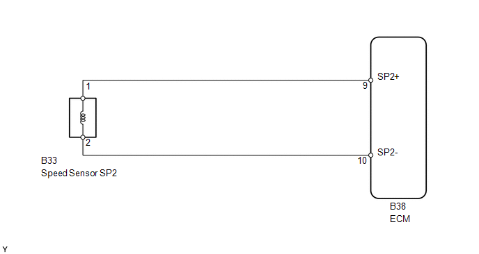
The speed sensor SP2 detects the rotation speed of the transmission output shaft and sends signals to the ECM. The ECM determines the vehicle speed based on these signals. An AC voltage is generated in the speed sensor SP2 coil as the parking gear mounted on the rear planetary gear assembly rotates, and this voltage is sent to the ECM. The parking gear on the rear planetary gear is used as the timing rotor for this sensor.
The gear shift point and lock-up timing are controlled by the ECM based on the signals from this vehicle speed sensor and the throttle position sensor signal.
|
DTC Code |
DTC Detection Condition |
Trouble Area |
|---|---|---|
|
P0722 |
All conditions are met 500 times or more continuously (2-trip detection logic): (a) No signal from speed sensor SP2 is input to the ECM while 4 pulses of the No. 1 vehicle speed sensor signal are sent. (b) Vehicle speed is 9 km/h (6 mph) or more for at least 5 sec. (c) Park/neutral position switch is OFF. |
|
Reference: Inspect using an oscilloscope.
Check the waveform of the ECM connector.
Standard:
|
Terminal No. (Symbol) |
Tool Setting |
Condition |
Specified Condition |
|---|---|---|---|
|
B38-9 (SP2+) - B38-10 (SP2-) |
2 V/DIV., 20 msec./DIV. |
Vehicle speed 20 km/h (12 mph) |
Refer to illustration |
.png)
MONITOR DESCRIPTION
The output speed sensor SP2 monitors the output shaft speed. The ECM controls the gear shift point and lock-up timing based on the signals from the output speed sensor SP2 and throttle position sensor.
If the ECM detects no signal from the output shaft speed sensor SP2 even while the vehicle is moving, it will conclude that there is a malfunction of the output speed sensor SP2. The ECM will illuminate the MIL and store a DTC.
MONITOR STRATEGY
|
Related DTCs |
P0722: Speed sensor SP2/Verify pulse input |
|
Required Sensors/Components |
Speed sensor SP2 |
|
Frequency of operation |
Continuous |
|
Duration |
5 sec. |
|
MIL operation |
2 driving cycles |
|
Sequence of operation |
None |
TYPICAL ENABLING CONDITIONS
|
The monitor will run whenever the following DTCs are not stored |
None |
|
Vehicle speed from vehicle speed sensor |
9 km/h (5.59 mph) or more |
|
Battery voltage |
8 V or higher |
|
Ignition switch |
ON |
|
Starter |
OFF |
TYPICAL MALFUNCTION THRESHOLDS
|
Speed sensor signal |
No signal |
COMPONENT OPERATING RANGE
|
Vehicle speed from output speed sensor |
9 km/h (5.59 mph) or more |
WIRING DIAGRAM
CAUTION / NOTICE / HINT
NOTICE:
Perform the universal trip to clear permanent DTCs (See page
.gif) ).
).
1. DATA LIST
HINT:
Using the Techstream to read the Data List allows the values or states of switches, sensors, actuators and other items to be read without removing any parts. This non-intrusive inspection can be very useful because intermittent conditions or signals may be discovered before parts or wiring is disturbed. Reading the Data List information early in troubleshooting is one way to save diagnostic time.
NOTICE:
In the table below, the values listed under "Normal Condition" are reference values. Do not depend solely on these reference values when deciding whether a part is faulty or not.
(a) Warm up the engine.
(b) Turn the ignition switch off.
(c) Connect the Techstream to the DLC3.
(d) Turn the ignition switch to ON.
(e) Turn the Techstream on.
(f) Enter the following menus: Powertrain / Engine and ECT / Data List.
(g) According to the display on the Techstream, read the Data List.
Engine and ECT|
Tester Display |
Measurement Item/Range |
Normal Condition |
Diagnostic Note |
|---|---|---|---|
|
SPD (SP2) |
Output shaft speed/ Min.: 0 km/h (0 mph) Max.: 255 km/h (158 mph) |
Vehicle stopped: 0 km/h (0 mph) (output shaft speed equal to vehicle speed) |
- |
HINT:
- SPD (SP2) is always 0 while driving:
Open or short in the sensor or circuit.
- The SPD (SP2) value displayed on the Techstream is much lower than the
actual vehicle speed:
Sensor trouble, improper installation or intermittent connection trouble in the circuit.
PROCEDURE
|
1. |
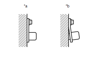
INSPECT SPEED SENSOR SP2 INSTALLATION |
|
(a) Check the speed sensor SP2 installation. OK: The installation bolt is tightened properly and there is no clearance between the sensor and transmission case. Text in Illustration
|
|
| NG | .gif) |
SECURELY INSTALL OR REPLACE SPEED SENSOR SP2 |
|
.gif)
|
2. |
INSPECT SPEED SENSOR SP2 |
|
(a) Disconnect the B33 speed sensor connector. |
|
(b) Measure the resistance according to the value(s) in the table below.
Standard Resistance:
|
Tester Connection |
Condition |
Specified Condition |
|---|---|---|
|
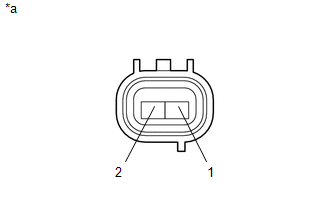
1 - 2 |
20°C (68°F) |
560 to 680 Ω |
|
*a |
Component without harness connected (Speed Sensor SP2) |
| NG | |
REPLACE SPEED SENSOR SP2 |
|
|
3. |
CHECK HARNESS AND CONNECTOR (SPEED SENSOR SP2 - ECM) |
|
(a) Disconnect the B38 ECM connector. |
|
(b) Measure the resistance according to the value(s) in the table below.
Standard Resistance:
|
Tester Connection |
Condition |
Specified Condition |
|---|---|---|
|
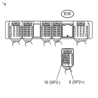
B38-9 (SP2+) - B38-10 (SP2-) |
20°C (68°F) |
560 to 680 Ω |
|
B38-9 (SP2+) - Body ground |
Always |
10 kΩ or higher |
|
B38-10 (SP2-) - Body ground |
Always |
10 kΩ or higher |
|
*a |
Rear view of wire harness connector (to ECM) |
| OK | |
REPLACE ECM |
| NG | |
REPAIR OR REPLACE HARNESS OR CONNECTOR |
 Pressure Control Solenoid "A" Electrical (Shift Solenoid Valve SL1) (P0748)
DESCRIPTION
Shifting from 1st to 5th is performed in combination with the ON and OFF operation
of the shift solenoid valves SL1, SL2, S1, S2 and SR, which are controlled by the
ECM. If an open or ...
 Turbine Speed Sensor Circuit No Signal (P0717)
DESCRIPTION
This sensor detects the rotation speed of the turbine which indicates the input
speed of the transmission. By comparing the input turbine speed signal NT with the
counter gear speed s ...
Other materials about Toyota 4Runner:
Removal
REMOVAL
CAUTION / NOTICE / HINT
HINT:
Use the same procedure for the RH and LH sides.
The procedure listed below is for the LH side.
PROCEDURE
1. REMOVE REAR WHEEL
2. DRAIN BRAKE FLUID
NOTICE:
Wash the brake fluid off immediately if i ...
Vehicle Speed Signal Circuit between Radio Receiver and Combination Meter
DESCRIPTION
for Automatic Sound Levelizer (ASL):
This circuit is necessary for the Automatic Sound Levelizer (ASL) built
into the radio and display receiver assembly.
The Automatic Sound Levelizer (ASL) function automatically adjusts the
a ...
0.0258