Toyota 4Runner: Inspection
INSPECTION
PROCEDURE
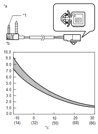
1. INSPECT NO. 1 COOLER THERMISTOR
|
(a) Measure the resistance according to the value(s) in the table below. Standard Resistance:
HINT: As the temperature increases, the resistance decreases (refer to the graph). NOTICE:
If the result is not as specified, replace the No. 1 cooler thermistor. Text in Illustration
|
|
 Removal
REMOVAL
PROCEDURE
1. REMOVE AIR CONDITIONING UNIT
(a) Remove the air conditioning unit (See page
).
...
 Installation
INSTALLATION
PROCEDURE
1. INSTALL AIR CONDITIONING UNIT
(a) Install the air conditioning unit (See page
).
...
Other materials about Toyota 4Runner:
Front Speed Sensor
Components
COMPONENTS
ILLUSTRATION
Removal
REMOVAL
CAUTION / NOTICE / HINT
HINT:
The procedure listed below is for the LH side.
Other than areas where instructions are provided, use the same procedures
for the RH and LH sides.
...
Room Light(for Front)
Components
COMPONENTS
ILLUSTRATION
Inspection
INSPECTION
PROCEDURE
1. INSPECT MAP LIGHT ASSEMBLY
(a) Measure the resistance according to the value(s) in the table below.
Standard Resistance:
Tester Connection
...
0.0252