Toyota 4Runner: Adjustment
ADJUSTMENT
CAUTION / NOTICE / HINT
HINT:
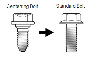
- Centering bolts are used to mount the hood hinge and hood lock. The hood and hood lock cannot be adjusted with the centering bolts installed. Substitute the centering bolts with standard bolts when making adjustments.
- The specified torque for standard bolts is shown in the standard bolt
chart (See page
.gif) ).
).
PROCEDURE
1. INSPECT HOOD SUB-ASSEMBLY
2. REMOVE UPPER RADIATOR SUPPORT SEAL
3. REMOVE FRONT BUMPER COVER (w/o Intuitive Parking Assist System)
4. REMOVE FRONT BUMPER COVER (w/ Intuitive Parking Assist System)
5. ADJUST HOOD SUB-ASSEMBLY
(a) Adjust the hood position.
|
(1) Loosen the 4 hinge bolts on the hood sub-assembly. |
|
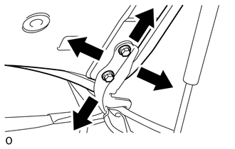
(2) Move the hood sub-assembly and adjust the clearance between the hood sub-assembly and front fender.
(3) Tighten the 4 hinge bolts on the hood sub-assembly after the adjustment.
Torque:
13 N·m {133 kgf·cm, 10 ft·lbf}
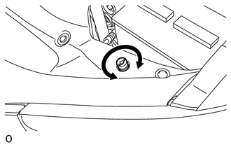
(b) Adjust the height of the front end of the hood sub-assembly using the cushion rubbers.
|
(1) Adjust the cushion rubbers so that the hood sub-assembly and front fender are aligned. HINT: Raise or lower the front end of the hood sub-assembly by turning the 2 cushion rubbers. |
|
(c) Adjust the hood lock.
|
(1) Loosen the 3 bolts. |
|
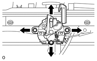
(2) Adjust the hood lock assembly and tighten the 3 bolts.
Torque:
7.5 N·m {76 kgf·cm, 66 in·lbf}
(3) Check that the striker can engage with the hood lock assembly smoothly.
6. INSTALL FRONT BUMPER COVER (w/ Intuitive Parking Assist System)
7. INSTALL FRONT BUMPER COVER (w/o Intuitive Parking Assist System)
8. INSTALL UPPER RADIATOR SUPPORT SEAL
 On-vehicle Inspection
ON-VEHICLE INSPECTION
PROCEDURE
1. INSPECT HOOD SUB-ASSEMBLY
(a) Check that the clearance measurements of areas A through E are within each
standard range.
Standard:
Area
...
 Reassembly
REASSEMBLY
CAUTION / NOTICE / HINT
NOTICE:
When installing the hood bulge protector, heat the hood bulge surface using a
heat light.
Standard:
Item
Temperature
...
Other materials about Toyota 4Runner:
On-vehicle Inspection
ON-VEHICLE INSPECTION
PROCEDURE
1. INSPECT DRIVE BELT
(a) Visually check the belt for excessive wear, frayed cords, etc.
If any defect is found, replace the drive belt.
HINT:
Cracks on the rib side of a belt are considered acceptable. Replace the belt
...
Using the AUX port
This port can be used to connect a portable audio device and listen to it
through the vehicle’s speakers.
Pull up the lid.
Open the cover and connect the portable audio device.
Press
or
.
Operating portable audio devices connected to the audio ...

0.0082