Toyota 4Runner: On-vehicle Inspection
ON-VEHICLE INSPECTION
PROCEDURE
1. INSPECT HOOD SUB-ASSEMBLY
(a) Check that the clearance measurements of areas A through E are within each standard range.
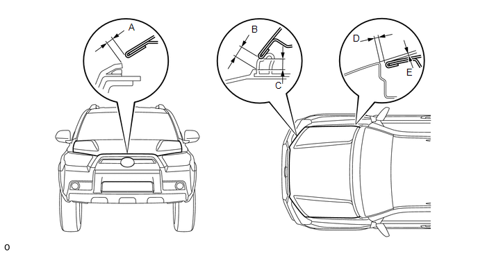
Standard:
|
Area |
Measurement |
Area |
Measurement |
|---|---|---|---|
|
A |
3.65 to 7.65 mm (0.144 to 0.301 in.) |
B |
5.15 to 9.15 mm (0.203 to 0.360 in.) |
|
C |
4.05 to 8.05 mm (0.165 to 0.323 in.) |
D |
2.0 to 5.0 mm (0.0787 to 0.197 in.) |
|
E |
-1.5 to 1.5 mm (-0.0591 to 0.0591 in.) |
- |
- |
 Disassembly
DISASSEMBLY
PROCEDURE
1. REMOVE HOOD TO RADIATOR SUPPORT SEAL
(a) Using a clip remover, remove the 7 clips and hood to radiator support
seal.
NOTICE:
If the clips are damaged o ...
 Adjustment
ADJUSTMENT
CAUTION / NOTICE / HINT
HINT:
Centering bolts are used to mount the hood hinge and hood lock. The
hood and hood lock cannot be adjusted with the centering bolts installed. ...
Other materials about Toyota 4Runner:
Removal
REMOVAL
PROCEDURE
1. DISCONNECT CABLE FROM NEGATIVE BATTERY TERMINAL
CAUTION:
Wait at least 90 seconds after disconnecting the cable from the negative (-)
battery terminal to disable the SRS system.
NOTICE:
When disconnecting the cable, some systems ne ...
Removal
REMOVAL
PROCEDURE
1. REMOVE FRONT DOOR LOWER FRAME BRACKET GARNISH RH
(a) Detach the 2 clips and remove the front door lower frame bracket
garnish RH.
2. REMOVE DOOR NO. 2 INSIDE HANDLE BEZEL RH
...

0.0269