Toyota 4Runner: Air Conditioning Pressure Sensor
Components
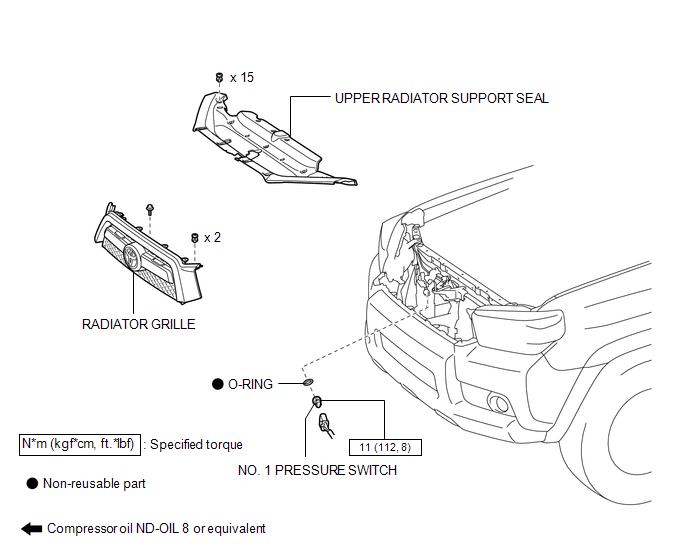
COMPONENTS
ILLUSTRATION
On-vehicle Inspection
ON-VEHICLE INSPECTION
PROCEDURE
1. INSPECT NO. 1 PRESSURE SWITCH
|
(a) Connect a manifold gauge set. |
|
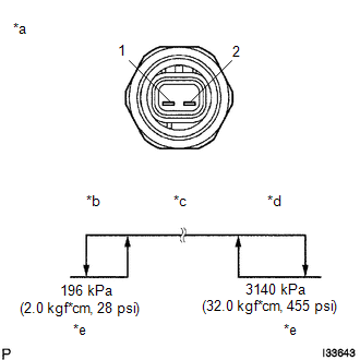
(b) Connect the positive (+) lead from the ohmmeter to terminal 1 and the negative (-) lead to terminal 2.
(c) Measure the resistance between terminals when refrigerant pressure is charged, as shown in the illustration.
If operation is not as specified, replace the pressure switch.
Text in Illustration|
*a |
Component without harness connected (No. 1 Pressure Switch) |
|
*b |
Low Pressure Side |
|
*c |
On (Below 1.0 Ω) |
|
*d |
High Pressure Side |
|
*e |
Off (10 kΩ or higher) |
Installation
INSTALLATION
PROCEDURE
1. INSTALL NO. 1 PRESSURE SWITCH
(a) Sufficiently apply compressor oil to a new O-ring and the fitting surface of the No. 1 pressure switch.
Compressor oil:
ND-OIL 8 or equivalent
(b) Install the O-ring to the No. 1 pressure switch.
(c) Install the No. 1 pressure switch.
Torque:
11 N·m {112 kgf·cm, 8 ft·lbf}
(d) Connect the connector.
2. CHARGE REFRIGERANT
.gif)
3. WARM UP ENGINE
4. CHECK FOR REFRIGERANT GAS LEAK
5. INSTALL RADIATOR GRILLE
(a) Install the radiator grille (See page ).
6. INSTALL UPPER RADIATOR SUPPORT SEAL
Removal
REMOVAL
PROCEDURE
1. REMOVE UPPER RADIATOR SUPPORT SEAL
.gif)
2. REMOVE RADIATOR GRILLE
(a) Remove the radiator grille (See page ).
3. RECOVER REFRIGERANT FROM REFRIGERATION SYSTEM
4. REMOVE NO. 1 PRESSURE SWITCH
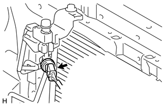
(a) Disconnect the connector.
(b) Remove the No. 1 pressure switch.
(c) Remove the O-ring from the No. 1 pressure switch.
NOTICE:
Seal the openings of the disconnected parts using vinyl tape to prevent moisture and foreign matter from entering them.
 Air Conditioning Panel
Components
COMPONENTS
ILLUSTRATION
Installation
INSTALLATION
PROCEDURE
1. INSTALL HEATER CONTROL ASSEMBLY
(a) Attach the 4 clips to install the heater control assembly.
...

Other materials about Toyota 4Runner:
Installation
INSTALLATION
PROCEDURE
1. INSTALL DOOR CONTROL SWITCH ASSEMBLY
(a) Attach the 2 claws to install the door control switch assembly.
(b) Connect the door control switch connector.
2. INSTALL FRONT DO ...
Acn Call End
ACN CALL END
1. ACN CALL END
This function terminates the ACN (Automatic Collision Notification) to the telematics
provider. After a collision in which the DCM receives a "Collision Detection Signal",
the vehicle will send the emergency call no ...

0.0262