Toyota 4Runner: Air Conditioning Panel
Components
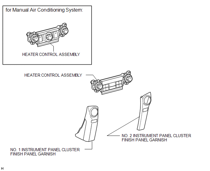
COMPONENTS
ILLUSTRATION
Installation
INSTALLATION
PROCEDURE
1. INSTALL HEATER CONTROL ASSEMBLY
|
(a) Attach the 4 clips to install the heater control assembly. |
|
2. INSTALL NO. 1 INSTRUMENT PANEL CLUSTER FINISH PANEL GARNISH
.gif)
3. INSTALL NO. 2 INSTRUMENT CLUSTER FINISH PANEL GARNISH
(a) Attach the 5 clips to install the No. 2 instrument cluster finish panel garnish.
Removal
REMOVAL
PROCEDURE
1. REMOVE NO. 1 INSTRUMENT PANEL CLUSTER FINISH PANEL GARNISH
.gif)
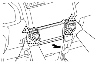
2. REMOVE NO. 2 INSTRUMENT PANEL CLUSTER FINISH PANEL GARNISH
(a) Open the instrument cluster finish panel lid.
(b) Put protective tape around the No. 2 instrument cluster finish panel garnish.
(c) Grip the No. 2 instrument cluster finish panel garnish and pull it diagonally upward toward the rear to detach the 5 clips and remove the No. 2 instrument cluster finish panel garnish.
.png) Text in Illustration
Text in Illustration
|
*1 |
Protective Tape |
- |
- |
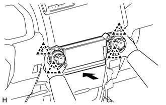
3. REMOVE HEATER CONTROL ASSEMBLY
|
(a) Detach the 4 clips and remove the heater control assembly. |
|
 Removal
REMOVAL
PROCEDURE
1. DISCONNECT CABLE FROM NEGATIVE BATTERY TERMINAL
CAUTION:
Wait at least 90 seconds after disconnecting the cable from the negative (-)
battery terminal to disable the SRS sys ...
 Air Conditioning Pressure Sensor
Components
COMPONENTS
ILLUSTRATION
On-vehicle Inspection
ON-VEHICLE INSPECTION
PROCEDURE
1. INSPECT NO. 1 PRESSURE SWITCH
(a) Connect a manifold gauge set.
...
Other materials about Toyota 4Runner:
Removal
REMOVAL
CAUTION / NOTICE / HINT
PROCEDURE
1. REMOVE STEERING WHEEL ASSEMBLY
(a) Remove the steering wheel assembly (See page
).
2. REMOVE LOWER STEERING COLUMN COVER
3. REMOVE UPPER STEERING COLUMN COVER
4. REMOVE SPIRAL CABLE SUB-ASSEMBLY
...
Reassembly
REASSEMBLY
CAUTION / NOTICE / HINT
HINT:
Use the same procedure for the RH and LH sides.
The procedure listed below is for the LH side.
When installing the pad, heat the moulding surface using a heat light.
Standard:
I ...

0.0076