Toyota 4Runner: A-TRAC Indicator Light Remains ON
DESCRIPTION
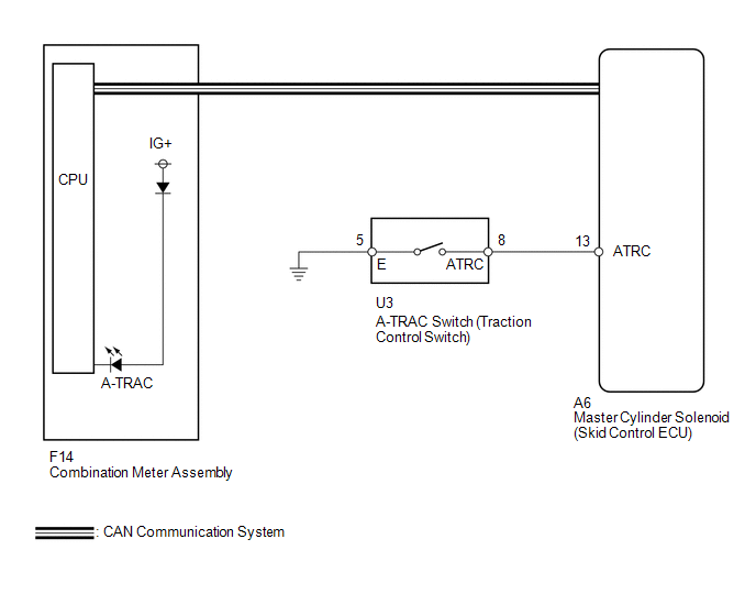
This is the A-TRAC main switch circuit. When the A-TRAC switch is turned on with the transfer in L4, the A-TRAC function is available and the A-TRAC indicator light illuminates.
WIRING DIAGRAM
CAUTION / NOTICE / HINT
NOTICE:
When replacing the master cylinder solenoid, perform calibration (See page
.gif) ).
).
PROCEDURE
|
1. |
CHECK CAN COMMUNICATION LINE |
(a) Turn the ignition switch off.
(b) Connect the Techstream to the DLC3.
(c) Turn the ignition switch to ON.
(d) Turn the Techstream on.
(e) Select CAN Bus Check from the System Selection Menu screen and follow the
prompts on the screen to inspect the CAN bus (See page
).
OK:
CAN Bus Check indicates no malfunctions in CAN communication.
| NG | .gif) |
GO TO CAN COMMUNICATION SYSTEM (HOW TO PROCEED WITH TROUBLESHOOTING) |
|
.gif)
|
2. |
INSPECT TRACTION CONTROL SWITCH (A-TRAC SWITCH) |
(a) Remove the A-TRAC switch (See page ).
|
(b) Measure the resistance according to the value(s) in the table below. Standard Resistance:
|
|
| NG | |
REPLACE TRACTION CONTROL SWITCH (A-TRAC SWITCH) |
|
|
3. |
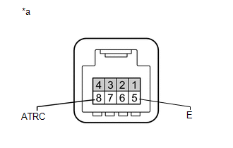
CHECK HARNESS AND CONNECTOR (SKID CONTROL ECU - A-TRAC SWITCH) |
(a) Disconnect the A6 skid control ECU connector.
(b) Disconnect the U3 A-TRAC switch connector.
(c) Measure the resistance according to the value(s) in the table below.
Standard Resistance:
|
Tester Connection |
Condition |
Specified Condition |
|---|---|---|
|
A6-13 (ATRC) - U3-8 (ATRC) |
Always |
Below 1 Ω |
|
A6-13 (ATRC) - Body ground |
Always |
10 k Ω or higher |
|
U3-5 (E) - Body ground |
Always |
Below 1 Ω |
| NG | |
REPAIR OR REPLACE HARNESS OR CONNECTOR |
|
|
4. |
READ VALUE USING TECHSTREAM (A-TRAC INDICATOR LIGHT) |
(a) Turn the ignition switch off.
(b) Connect the Techstream to the DLC3.
(c) Turn the ignition switch to ON.
(d) Turn the Techstream on.
(e) Enter the following menus: Chassis / ABS/VSC/TRAC / Data List.
(f) Check the condition of the A-TRAC switch by operating the Techstream.
ABS/VSC/TRAC|
Tester Display |
Measurement Item/Range |
Normal Condition |
Diagnostic Note |
|---|---|---|---|
|
A-TRAC Indicator Light |
A-TRAC indicator light/ ON or OFF |
ON: Indicator light on ON: Indicator light off |
- |
OK:
The Techstream displays ON or OFF according to A-TRAC switch operation.
| OK | |
GO TO METER / GAUGE SYSTEM (HOW TO PROCEED WITH TROUBLESHOOTING) |
| NG | |
REPLACE MASTER CYLINDER SOLENOID |
 AUTO LSD Indicator Light Remains ON
DESCRIPTION
During normal mode, pressing the VSC OFF switch for a short amount of time changes
vehicle to AUTO LSD mode.
WIRING DIAGRAM
CAUTION / NOTICE / HINT
NOTICE:
When replacing the mast ...
 AUTO LSD Indicator Light does not Come ON
DESCRIPTION
The AUTO LSD does not operate even if the VSC OFF switch is pressed under the
following conditions:
The brake system is faulty.
The temperature inside the hydraulic brake bo ...
Other materials about Toyota 4Runner:
Removal
REMOVAL
PROCEDURE
1. DISCONNECT CABLE FROM NEGATIVE BATTERY TERMINAL
CAUTION:
Wait at least 90 seconds after disconnecting the cable from the negative (-)
battery terminal to disable the SRS system (See page
).
NOTICE:
When disconnecting the cable, s ...
Room Light(for Rear)
Components
COMPONENTS
ILLUSTRATION
Installation
INSTALLATION
PROCEDURE
1. INSTALL NO. 1 ROOM LIGHT ASSEMBLY
(a) Align the switch parts as shown in the illustration and attach the
4 claws to install the room light switch base to the ...

0.0095