Toyota 4Runner: Automatic door locking and unlocking systems
The following functions can be set or canceled:
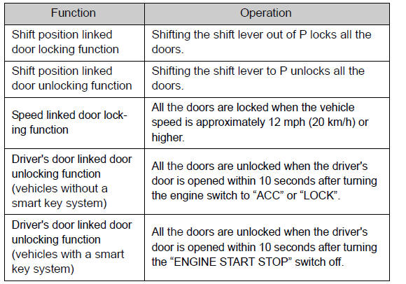
Setting and canceling the functions
To switch between setting and canceling, follow the procedure below:

Vehicles without a smart key system
Close all the doors and turn the engine switch to the “ON” position. (Perform step 2 within 20 seconds.)
Vehicles with a smart key system
Close all the doors and turn the “ENGINE START STOP” switch to IGNITION ON mode. (Perform step 2 within 20 seconds.)
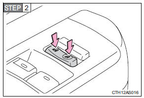
Shift the shift lever to P or N, and press and hold the driver's door lock
switch (  or
or
 ) for approximately 5 seconds and
then release.
The shift lever and switch positions corresponding to the desired function to be set are shown in the following table.
Use the same procedure to cancel the function.
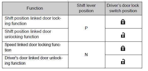
When the setting or canceling operation is complete, all the doors are locked and then unlocked.
Using the mechanical key (vehicles with a smart key system)
The doors can also be locked and unlocked with the mechanical key.
Customization that can be configured at Toyota dealer
Settings (e.g. door unlocking function) can be changed.
(Customizable features )
CAUTION
To prevent an accident
Observe the following precautions while driving the vehicle.
Failure to do so may result in a door opening and an occupant falling out, resulting in death or serious injury.
• Always use a seat belt.
• Always lock all the doors.
• Ensure that all doors are properly closed before driving.
• Do not pull the inside handle of the doors while driving.
The doors may be opened and the passengers are thrown out of the vehicle and it may result in death or serious injury.
Be especially careful for the front doors, as the doors may be opened even if the inside lock buttons are in locked position.
• Set the rear door child-protector locks when children are seated in the rear
seats.
 Rear door child-protector lock
The door cannot be opened from inside the vehicle when the lock is set.
1. Unlock
2. Lock
These locks can be set to prevent children from opening the rear doors. Push
down on each rear door sw ...
 Automatic running boards
The Automatic running boards are linked to the side door operations,
extending and retracting when a side door is opened and closed. When a door is
opened or closed, the board on the same side ext ...
Other materials about Toyota 4Runner:
On-vehicle Inspection
ON-VEHICLE INSPECTION
PROCEDURE
1. CHECK REAR FLOOR SIDE AIRBAG SENSOR (VEHICLE NOT INVOLVED IN COLLISION)
(a) Perform a diagnostic system check (See page
).
2. CHECK REAR FLOOR SIDE AIRBAG SENSOR (VEHICLE INVOLVED IN COLLISION AND AIRBAG
HAS NOT DEPLO ...
Active traction control system
The active traction control system automatically helps prevent the
spinning of 4 wheels when the vehicle is started or accelerated on slippery road
surfaces.
System operation
Part-time 4WD models:
Stop the vehicle, shift the shift lever to N and shift ...

0.0167