Toyota 4Runner: Terminals Of Ecu
TERMINALS OF ECU
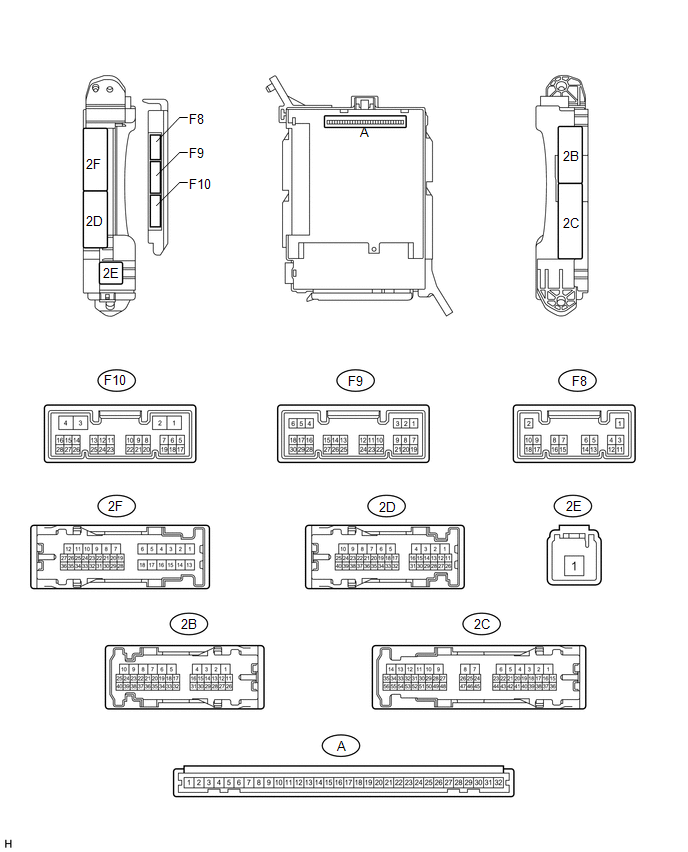
1. CHECK DRIVER SIDE JUNCTION BLOCK ASSEMBLY AND MAIN BODY ECU (MULTIPLEX NETWORK BODY ECU)
(a) Measure the voltage according to the value(s) in the table below.
|
Terminal No. (Symbol) |
Wiring Color |
Terminal Description |
Condition |
Specified Condition |
|---|---|---|---|---|
|
F9-15 (SPD) - 2B-4 (GND1) |
R - W-B |
Speed signal |
Vehicle speed at lower than 8 km/h (5 mph) |
11 to 14 V |
|
Vehicle speed at 8 km/h (5 mph) or more |
Below 1 V |
If the result is not as specified, the main body ECU may have a malfunction.
2. CHECK SIDE AUTO STEP CONTROLLER ECU ASSEMBLY
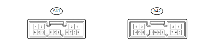
(a) Disconnect the A41 side auto step controller ECU assembly connector.
(b) Measure the voltage and resistance according to the value(s) in the table below.
|
Terminal No. (Symbol) |
Wiring Color |
Terminal Description |
Condition |
Specified Condition |
|---|---|---|---|---|
|
A41-1 (GND) - Body Ground |
W-B - Body Ground |
Ground |
Always |
Below 1 Ω |
|
A41-4 (B) - A41-1 (GND) |
L - W-B |
Battery power supply |
Always |
11 to 14 V |
HINT:
If the result is not as specified, there may be a malfunction on the wire harness side.
(c) Reconnect the A41 side auto step controller ECU assembly connector.
(d) Measure the voltage and resistance according to the value(s) in the table below.
|
Terminal No. (Symbol) |
Wiring Color |
Terminal Description |
Condition |
Specified Condition |
|---|---|---|---|---|
|
A41-5 (SSR-) - A41-1 (GND) |
GR - W-B |
Ground |
Always |
Below 1 Ω |
|
A41-9 (SSR2) - A41-1 (GND) |
L - W-B |
Side auto step motor hall sensor RH signal |
When the automatic running board RH is being deployed or stowed |
Pulse generation (See waveform 1) |
|
A41-10 (SSR1) - A41-1 (GND) |
W - W-B |
Side auto step motor hall sensor LH signal |
When the automatic running board LH is being deployed or stowed |
Pulse generation (See waveform 1) |
|
A41-14 (SSR+) - A41-1 (GND) |
LG - W-B |
Side auto step hall sensor power supply |
When the automatic running board is being deployed or stowed |
8 to 11 V |
|
A42-1 (DPL2) - A41-1 (GND) |
G - W-B |
Side auto step motor RH operation signal |
Passenger side door is opened When the automatic running board RH is being deployed |
11 to 14 V |
|
A42-2 (STW2) - A41-1 (GND) |
R - W-B |
Side auto step motor RH operation signal |
Passenger side door is closed When the automatic running board RH is being stowed |
11 to 14 V |
|
A42-3 (STW1) - A41-1 (GND) |
P - W-B |
Side auto step motor LH operation signal |
Driver side door is closed When the automatic running board LH is being stowed |
11 to 14 V |
|
A42-4 (DPL1) - A41-1 (GND) |
V - W-B |
Side auto step motor LH operation signal |
Driver side door is opened When the automatic running board LH is being deployed |
11 to 14 V |
|
A42-9 (FOUT) - A41-1 (GND) |
GR - W-B |
Ground |
Always |
Below 1 V |
|
A42-10 (FIN) - A41-1 (GND) |
W - W-B |
Ground |
Always |
Below 1 V |
|
A42-11 (SP1+) - A41-1 (GND) |
R - W-B |
Speed signal |
Vehicle speed at lower than 8 km/h (5 mph) |
11 to 14 V |
|
Vehicle speed at 8 km/h (5 mph) or more |
Below 1 V |
|||
|
A42-12 (IND) - A41-1 (GND) |
G - W-B |
Warning light drive output |
Warning light on |
11 to 14 V |
|
Warning light off |
Below 1 V |
|||
|
A42-13 (CTY2) - A41-1 (GND) |
R - W-B |
Door courtesy light switch RH signal |
Rear door RH open |
Below 1 V |
|
Rear door RH closed |
11 to 14 V |
|||
|
A42-14 (CTY1) - A41-1 (GND) |
L - W-B |
Door courtesy light switch LH signal |
Rear door LH open |
Below 1 V |
|
Rear door LH closed |
11 to 14 V |
(e) Using an oscilloscope, check the waveform 1.
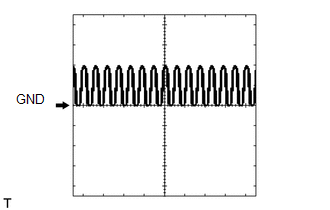 Waveform 1 (Reference)
|
Item |
Content |
|---|---|
|
Tool Setting |
5 V/DIV., 5 ms/DIV. |
|
Condition |
When the automatic running board is being deployed or stowed |
 Problem Symptoms Table
PROBLEM SYMPTOMS TABLE
HINT:
Use the table below to help determine the cause of problem symptoms.
If multiple suspected areas are listed, the potential causes of the symptoms
are lis ...
 Diagnosis System
DIAGNOSIS SYSTEM
1. FUNCTION OF AUTOMATIC RUNNING BOARD WARNING LIGHT
(a) When a malfunction is detected in the automatic running board system, the
automatic running board warning light in the com ...
Other materials about Toyota 4Runner:
Side doors
The vehicle can be locked and unlocked using the entry function, wireless
remote control, key or door lock switch.
Entry function (vehicles with a smart key system)
Wireless remote control
Key
Turning the key operates the doors as follows:
Vehicles ...
Precaution
PRECAUTION
CAUTION:
Replace any faulty parts of the seat belt systems (outer belt, inner belt, bolts,
nuts, adjustable shoulder anchor, tether anchor hardware and other related parts).
When inspecting a vehicle that was in a collision, be sure to check a ...

0.0255