Toyota 4Runner: AV Signal Stoppage (Low Battery Voltage) (B158F)
DESCRIPTION
This DTC is stored when a video or audio signal is interrupted due to battery voltage input to the navigation receiver assembly dropping temporarily.
|
DTC No. |
DTC Detection Condition |
Trouble Area |
|---|---|---|
|
B158F |
A video or audio signal is interrupted when the battery voltage drops. |
|
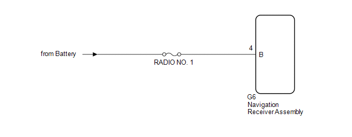
WIRING DIAGRAM
CAUTION / NOTICE / HINT
NOTICE:
- After replacing the navigation receiver assembly of vehicles subscribed to pay-type satellite radio broadcasts, registration of the XM radio ID is necessary.
- Inspect the fuses for circuits related to this system before performing the following procedure.
PROCEDURE
|
1. |
CHECK VEHICLE SIGNAL (OPERATION CHECK) |
|
(a) Enter the "Vehicle Signal Check Mode" screen. Refer to Check Vehicle
Signal in Operation Check (See page |
|
.png)
(b) Check the battery voltage.
Standard Voltage:
11 to 14 V
HINT:
This display is updated once per second.
| NG | .gif) |
GO TO STEP 3 |
|
.gif)
|
2. |
CHECK DTC |
(a) Clear the DTCs (See page .gif) ).
).
(b) Recheck for DTCs and check if the same DTC are output again.
OK:
No DTCs are output.
| OK | |
USE SIMULATION METHOD TO CHECK |
| NG | |
REPLACE NAVIGATION RECEIVER ASSEMBLY |
|
3. |
CHECK HARNESS AND CONNECTOR (NAVIGATION RECEIVER ASSEMBLY POWER SOURCE) |
(a) Disconnect the G6 navigation receiver assembly connector.
(b) Measure the voltage according to the value(s) in the table below.
Standard Voltage:
|
Tester Connection |
Condition |
Specified Condition |
|---|---|---|
|
G6-4 (B) - Body ground |
Always |
11 to 14 V |
| OK | |
REPLACE NAVIGATION RECEIVER ASSEMBLY |
| NG | |
REPAIR OR REPLACE HARNESS AND CONNECTOR |
 SD Card Communication Malfunction (B158C)
DESCRIPTION
The navigation receiver assembly stores this DTC when the SD card cannot be mounted
when inserted into the SD card slot.
DTC No.
DTC Detection Condition
...
 Stereo Component Amplifier Malfunction (B15A3)
DESCRIPTION
This DTC is stored when a malfunction occurs in the stereo component amplifier
assembly.
DTC No.
DTC Detection Condition
Trouble Area
...
Other materials about Toyota 4Runner:
Installation
INSTALLATION
CAUTION / NOTICE / HINT
CAUTION:
Wear protective gloves. Sharp areas on the parts may injure your hands.
HINT:
A bolt without a torque specification is shown in the standard bolt chart (See
page ).
PROCEDURE
1. INSTALL REAR NO. 1 SEAT IN ...
Auto Up / Down Function does not Operate
DESCRIPTION
If the auto up/down function does not operate, the cause may be one or more of
the following:
The ECU in the back door power window regulator motor determines that
the back door power window regulator motor has not been initialized.
...

0.0255