Toyota 4Runner: LIN Communication Bus Malfunction (B2325)
DESCRIPTION
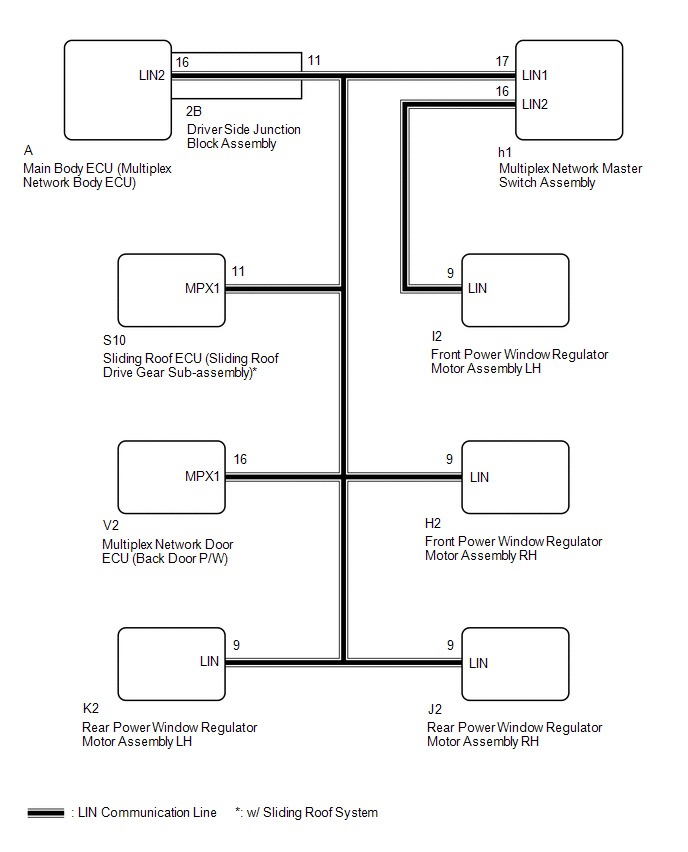
The main body ECU (multiplex network body ECU) intermittently monitors the LIN communication bus between the components related to the doors and sliding roof ECU (sliding roof drive gear sub-assembly)*. DTC B2325 is stored when a malfunction in the LIN communication bus between the components related to the doors and sliding roof ECU (sliding roof drive gear sub-assembly)* is detected consecutively 3 times.
- *: w/ Sliding Roof System
|
DTC Code |
DTC Detection Condition |
Trouble Area |
|---|---|---|
|
B2325 |
The main body ECU (multiplex network body ECU) detects a malfunction in the LIN communication bus between components related to the doors and sliding roof ECU (sliding roof drive gear sub-assembly)* consecutively 3 times. |
|
- *: w/ Sliding Roof System
WIRING DIAGRAM
CAUTION / NOTICE / HINT
NOTICE:
- When using the Techstream with the ignition switch off to troubleshoot:
Connect the Techstream to the vehicle and turn a courtesy light switch on and off at 1.5 second intervals until communication between the Techstream and vehicle begins.
- Inspect the fuses and bulbs for circuits related to this system before performing the following inspection procedure.
HINT:
When DTC B2325 and a LIN communication stop DTC are output simultaneously, first perform troubleshooting for the LIN communication stop DTC. Then perform troubleshooting for DTC B2325.
PROCEDURE
|
1. |
CLEAR DTC |
(a) Clear the DTCs (See page .gif) ).
).
|
.gif)
|
2. |
CHECK FOR DTC |
(a) Check for DTCs (See page ).
OK:
DTC B2325 is not output.
| OK | .gif) |
USE SIMULATION METHOD TO CHECK |
|
|
3. |
CHECK DRIVER SIDE JUNCTION BLOCK ASSEMBLY |
(a) Remove the main body ECU (multiplex network body ECU) from the driver side
junction block assembly (See page ).
(b) Measure the resistance according to the value(s) in the table below.
Standard Resistance:
|
Tester Connection |
Condition |
Specified Condition |
|---|---|---|
|
A-16 (LIN2) - 2B-11 |
Always |
Below 1 Ω |
|
A-16 (LIN2) or 2B-11 - Body ground |
Always |
10 kΩ or higher |
| NG | |
REPLACE DRIVER SIDE JUNCTION BLOCK ASSEMBLY |
|
|
4. |
CLEAR DTC |
(a) Install the main body ECU (multiplex network body ECU) to the driver side
junction block assembly (See page ).
(b) Disconnect the I2 front power window regulator motor assembly LH connector.
(c) Clear the DTCs (See page ).
|
|
5. |
CHECK FOR DTC |
(a) Check for DTCs (See page ).
Result
|
Result |
Proceed to |
|---|---|
|
DTC B2325 is output |
A |
|
DTC B2325 is not output |
B |
| B | |
REPLACE FRONT POWER WINDOW REGULATOR MOTOR ASSEMBLY LH |
|
|
6. |
CLEAR DTC |
(a) Connect the I2 front power window regulator motor assembly LH connector.
(b) Disconnect the h1 multiplex network master switch assembly connector.
(c) Clear the DTCs (See page ).
|
|
7. |
CHECK FOR DTC |
(a) Check for DTCs (See page ).
Result
|
Result |
Proceed to |
|---|---|
|
DTC B2325 is output |
A |
|
DTC B2325 is not output |
B |
| B | |
REPLACE MULTIPLEX NETWORK MASTER SWITCH ASSEMBLY |
|
|
8. |
CLEAR DTC |
(a) Connect the h1 multiplex network master switch assembly connector.
(b) Disconnect the H2 front power window regulator motor assembly RH connector.
(c) Clear the DTCs (See page ).
|
|
9. |
CHECK FOR DTC |
(a) Check for DTCs (See page ).
Result
|
Result |
Proceed to |
|---|---|
|
DTC B2325 is output |
A |
|
DTC B2325 is not output |
B |
| B | |
REPLACE FRONT POWER WINDOW REGULATOR MOTOR ASSEMBLY RH |
|
|
10. |
CLEAR DTC |
(a) Connect the H2 front power window regulator motor assembly RH connector.
(b) Disconnect the J2 rear power window regulator motor assembly RH connector.
(c) Clear the DTCs (See page ).
|
|
11. |
CHECK FOR DTC |
(a) Check for DTCs (See page ).
Result
|
Result |
Proceed to |
|---|---|
|
DTC B2325 is output |
A |
|
DTC B2325 is not output |
B |
| B | |
REPLACE REAR POWER WINDOW REGULATOR MOTOR ASSEMBLY RH |
|
|
12. |
CLEAR DTC |
(a) Connect the J2 rear power window regulator motor assembly RH connector.
(b) Disconnect the K2 rear power window regulator motor assembly LH connector.
(c) Clear the DTCs (See page ).
|
|
13. |
CHECK FOR DTC |
(a) Check for DTCs (See page ).
Result
|
Result |
Proceed to |
|---|---|
|
DTC B2325 is output |
A |
|
DTC B2325 is not output |
B |
| B | |
REPLACE REAR POWER WINDOW REGULATOR MOTOR ASSEMBLY LH |
|
|
14. |
CLEAR DTC |
(a) Connect the K2 rear power window regulator motor assembly LH connector.
(b) Disconnect the V2 multiplex network door ECU (back door P/W) connector.
(c) Clear the DTCs (See page ).
|
|
15. |
CHECK FOR DTC |
(a) Check for DTCs (See page ).
Result
|
Result |
Proceed to |
|---|---|
|
DTC B2325 is output (w/ Sliding Roof System) |
A |
|
DTC B2325 is output (w/o Sliding Roof System) |
B |
|
DTC B2325 is not output |
C |
| B | |
REPLACE MAIN BODY ECU (MULTIPLEX NETWORK BODY ECU) |
| C | |
REPLACE MULTIPLEX NETWORK DOOR ECU (BACK DOOR P/W) |
|
|
16. |
CLEAR DTC |
(a) Connect the V2 multiplex network door ECU (back door P/W) connector.
(b) Disconnect the S10 sliding roof ECU (sliding roof drive gear sub-assembly) connector.
(c) Clear the DTCs (See page ).
|
|
17. |
CHECK FOR DTC |
(a) Check for DTCs (See page ).
Result
|
Result |
Proceed to |
|---|---|
|
DTC B2325 is output |
A |
|
DTC B2325 is not output |
B |
| A | |
REPLACE MAIN BODY ECU (MULTIPLEX NETWORK BODY ECU) |
| B | |
REPLACE SLIDING ROOF ECU (SLIDING ROOF DRIVE GEAR SUB-ASSEMBLY) |
 Back Door ECU Communication Stop (B1287)
DESCRIPTION
This DTC is stored when LIN communication between the multiplex network door
ECU (back door P/W) and main body ECU (multiplex network body ECU) stops for 10
seconds or more.
...
 Sliding Roof ECU Communication Stop (B1273)
DESCRIPTION
This DTC is stored when LIN communication between the sliding roof ECU (sliding
roof drive gear sub-assembly) and main body ECU (multiplex network body ECU) stops
for 10 seconds or mo ...
Other materials about Toyota 4Runner:
Outside rear view mirrors
Mirror angle can be adjusted using the switch.
To select a mirror to adjust, press the switch.
1. Left
2. Right
To adjust the mirror, press the switch.
1. Up
2. Right
3. Down
4. Left
Folding the mirrors
Push the mirror back in the direction ...
Short in GPS Antenna (B15C0,B15C1)
DESCRIPTION
This DTC is stored when the DCM (Telematics Transceiver) detects an open or a
short in the telephone and GPS antenna circuit. The DCM (Telematics Transceiver)
receives signals at a radio frequency of between 1574.42 and 1576.42 MHz through
t ...

0.015