Toyota 4Runner: Back Power Window Switch
Components
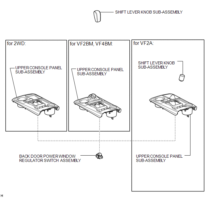
COMPONENTS
ILLUSTRATION
Removal
REMOVAL
PROCEDURE
1. REMOVE SHIFT LEVER KNOB SUB-ASSEMBLY
.gif)
2. REMOVE SHIFT LEVER KNOB SUB-ASSEMBLY (for VF2A)
3. REMOVE UPPER CONSOLE PANEL SUB-ASSEMBLY
4. REMOVE BACK DOOR POWER WINDOW REGULATOR SWITCH ASSEMBLY
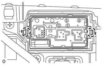
(a) Detach the 2 claws and remove the regulator switch.
Inspection
INSPECTION
PROCEDURE
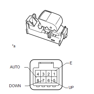
1. INSPECT BACK DOOR POWER WINDOW REGULATOR SWITCH ASSEMBLY
|
(a) Measure the resistance according to the value(s) in the table below. Standard Resistance:
|
|
Installation
INSTALLATION
PROCEDURE
1. INSTALL BACK DOOR POWER WINDOW REGULATOR SWITCH ASSEMBLY
(a) Attach the 2 claws to install the regulator switch.
2. INSTALL UPPER CONSOLE PANEL SUB-ASSEMBLY
.gif)
3. INSTALL SHIFT LEVER KNOB SUB-ASSEMBLY (for VF2A)
4. INSTALL SHIFT LEVER KNOB SUB-ASSEMBLY
 Installation
INSTALLATION
PROCEDURE
1. INSTALL BACK DOOR POWER WINDOW REGULATOR MOTOR ASSEMBLY
(a) Using a T25 "TORX" socket wrench, install the back power window regulator
motor assemb ...
 Front Passenger Side Power Window Switch
Components
COMPONENTS
ILLUSTRATION
Inspection
INSPECTION
PROCEDURE
1. INSPECT POWER WINDOW REGULATOR SWITCH ASSEMBLY
(a) Measure the resistance according to the value(s) in the ...
Other materials about Toyota 4Runner:
Rear Shock Absorber(w/o Reas)
Components
COMPONENTS
ILLUSTRATION
Removal
REMOVAL
CAUTION / NOTICE / HINT
HINT:
Use the same procedure for the RH and LH sides.
The procedure listed below is for the LH side.
PROCEDURE
1. REMOVE REAR WHEEL
2. REMOVE REAR SHOC ...
Vehicle Speed or Engine Speed Signal Malfunction (C2173/73)
DESCRIPTION
The tire pressure warning ECU receives a vehicle speed signal from the combination
meter and an engine speed signal from the ECM. The tire pressure warning ECU uses
these signals to store DTCs C2121/21 to C2124/24 or C2125/25*.
*: w/ S ...

0.0069