Toyota 4Runner: Installation
INSTALLATION
PROCEDURE
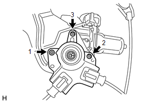
1. INSTALL BACK DOOR POWER WINDOW REGULATOR MOTOR ASSEMBLY
|
(a) Using a T25 "TORX" socket wrench, install the back power window regulator motor assembly with the 3 screws. HINT:
Torque: 5.5 N·m {56 kgf·cm, 49 in·lbf} |
|
2. INSTALL BACK DOOR POWER WINDOW REGULATOR SUB-ASSEMBLY
.gif)
3. INSTALL OUTER BACK DOOR GLASS WEATHERSTRIP ASSEMBLY
4. INSTALL BACK DOOR GLASS
5. INSTALL BACK DOOR GLASS RUN
6. INSTALL NO. 1 BACK WINDOW WIPER MOTOR BRACKET
7. INSTALL REAR WIPER MOTOR AND BRACKET ASSEMBLY
8. INSTALL REAR WIPER ARM
9. INSTALL REAR SPOILER SUB-ASSEMBLY
10. INSTALL REAR NO. 1 SPOILER COVER
11. INSTALL BACK DOOR OUTSIDE MOULDING LH
12. INSTALL BACK DOOR OUTSIDE MOULDING RH
HINT:
Use the same procedure as described for the LH side.
13. INSTALL BACK DOOR SERVICE HOLE COVER LH
14. INSTALL BACK DOOR SERVICE HOLE COVER RH
15. INSTALL NO. 2 BACK DOOR SERVICE HOLE COVER
16. INSTALL MULTIPLEX NETWORK DOOR ECU
17. INSTALL REAR NO. 2 SPEAKER ASSEMBLY
18. INSTALL BACK DOOR TRIM PANEL ASSEMBLY
19. INSTALL ASSIST STRAP ASSEMBLY
20. INSTALL ASSIST STRAP HOLE COVER
21. CONNECT CABLE TO NEGATIVE BATTERY TERMINAL
NOTICE:
When disconnecting the cable, some systems need to be initialized after the cable
is reconnected (See page ).
 Inspection
INSPECTION
PROCEDURE
1. INSPECT BACK DOOR POWER WINDOW REGULATOR MOTOR ASSEMBLY
(a) Check that the motor gear rotates smoothly as follows.
NOTICE:
Do not apply positive (+) battery ...
 Back Power Window Switch
Components
COMPONENTS
ILLUSTRATION
Removal
REMOVAL
PROCEDURE
1. REMOVE SHIFT LEVER KNOB SUB-ASSEMBLY
2. REMOVE SHIFT LEVER KNOB SUB-ASSEMBLY (for VF2A)
3. REMOVE UPPER CONSOLE PANE ...
Other materials about Toyota 4Runner:
Installation
INSTALLATION
CAUTION / NOTICE / HINT
HINT:
Use the same procedure for both the RH and LH sides.
The procedure listed below is for the LH side.
PROCEDURE
1. INSTALL FRONT FENDER MOULDING SUB-ASSEMBLY LH
(a) Install new 9 clips to the fro ...
Mute Signal Circuit between Stereo Component Amplifier and Telematics Transceiver
DESCRIPTION
The DCM (telematics transceiver) sends a mute signal to the stereo component
amplifier assembly.
The stereo component amplifier assembly controls the volume according to the
mute signal from the DCM (telematics transceiver).
WIRING DIAGRAM
...

0.0179