Toyota 4Runner: Front Passenger Side Power Window Switch
Components
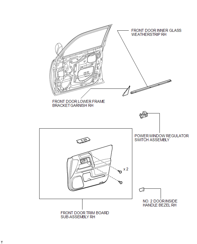
COMPONENTS
ILLUSTRATION
Inspection
INSPECTION
PROCEDURE
1. INSPECT POWER WINDOW REGULATOR SWITCH ASSEMBLY
|
(a) Measure the resistance according to the value(s) in the table below. Standard Resistance:
|
|
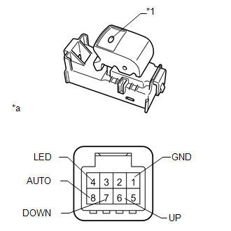
(b) Check that the LED illuminates.
(1) Apply battery voltage to the power window regulator switch and check that the LED illuminates.
OK:
|
Measurement Condition |
Specified Condition |
|---|---|
|
Battery positive (+) → 4 (LED) Battery negative (-) → 1 (GND) |
LED illuminates |
- If the result is not as specified, replace the power window regulator switch assembly.
|
*1 |
LED |
|
*a |
Front view of wire harness connector (Power Window Regulator Switch Assembly) |
Removal
REMOVAL
PROCEDURE
1. REMOVE FRONT DOOR LOWER FRAME BRACKET GARNISH RH
.gif)
2. REMOVE NO. 2 DOOR INSIDE HANDLE BEZEL RH
3. REMOVE FRONT DOOR TRIM BOARD SUB-ASSEMBLY RH
4. REMOVE FRONT DOOR INNER GLASS WEATHERSTRIP RH
5. REMOVE POWER WINDOW REGULATOR SWITCH ASSEMBLY
(a) Detach the 10 claws from the backside and remove the power window regulator switch with base panel.
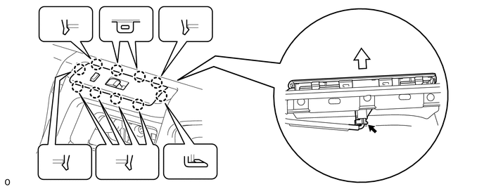
(b) Disconnect the connectors.
|
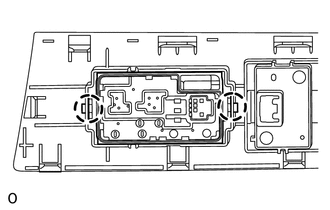
(c) Detach the 2 claws and remove the power window regulator switch. |
|
Installation
INSTALLATION
PROCEDURE
1. INSTALL POWER WINDOW REGULATOR SWITCH ASSEMBLY
(a) Attach the 2 claws to install the power window regulator switch.
(b) Connect the connectors.
(c) Attach the 10 claws to install the power window regulator switch with base panel.
2. INSTALL FRONT DOOR INNER GLASS WEATHERSTRIP RH
.gif)
3. INSTALL FRONT DOOR TRIM BOARD SUB-ASSEMBLY RH
4. INSTALL NO. 2 DOOR INSIDE HANDLE BEZEL RH
5. INSTALL FRONT DOOR LOWER FRAME BRACKET GARNISH RH
 Back Power Window Switch
Components
COMPONENTS
ILLUSTRATION
Removal
REMOVAL
PROCEDURE
1. REMOVE SHIFT LEVER KNOB SUB-ASSEMBLY
2. REMOVE SHIFT LEVER KNOB SUB-ASSEMBLY (for VF2A)
3. REMOVE UPPER CONSOLE PANE ...

Other materials about Toyota 4Runner:
Portable Player cannot be Connected Manually/Automatically
CAUTION / NOTICE / HINT
HINT:
Some versions of "Bluetooth" compatible audio players may not function, or the
function may be limited using the radio and display receiver assembly, even if the
portable audio player itself can play files (See pag ...
Problem Symptoms Table
PROBLEM SYMPTOMS TABLE
HINT:
Use the table below to help determine the cause of problem symptoms.
If multiple suspected areas are listed, the potential causes of the symptoms
are listed in order of probability in the "Suspected Area" ...

0.0277