Toyota 4Runner: Brake Actuator (Skid Control ECU) Communication Stop Mode
DESCRIPTION
|
Detection Item |
Symptom |
Trouble Area |
|---|---|---|
|
Brake Actuator (Skid Control ECU) Communication Stop Mode |
Either condition is met:
|
|
WIRING DIAGRAM

CAUTION / NOTICE / HINT
NOTICE:
Inspect the fuses for circuits related to this system before performing the following inspection procedure.
HINT:
Operating the ignition switch, any switches or any doors triggers related ECU and sensor communication with the CAN, which causes resistance variation.
PROCEDURE
|
1. |
DISCONNECT CABLE FROM NEGATIVE BATTERY TERMINAL |
(a) Disconnect the cable from the negative (-) battery terminal before measuring the resistances of the main wire and branch wire.
CAUTION:
Wait at least 90 seconds after disconnecting the cable from the negative (-) battery terminal to disable the SRS system.
NOTICE:
When disconnecting the cable, some systems need to be initialized after the cable
is reconnected (See page .gif) ).
).
|
.gif)
|
2. |
CHECK FOR OPEN IN CAN BUS WIRE (SKID CONTROL ECU BRANCH WIRE) |
|
(a) Disconnect the A53 skid control ECU (brake actuator assembly) connector. |
|
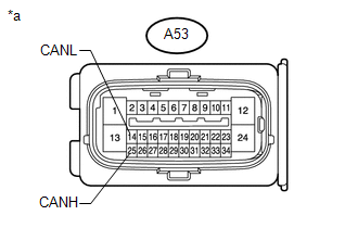
(b) Measure the resistance according to the value(s) in the table below.
Standard Resistance:
|
Tester Connection |
Switch Condition |
Specified Condition |
|---|---|---|
|
A53-25 (CANH) - A53-14 (CANL) |
Ignition switch off |
54 to 69 Ω |
|
*a |
Front view of wire harness connector (to Skid Control ECU [Brake Actuator Assembly]) |
| NG | .gif) |
REPAIR OR REPLACE SKID CONTROL ECU BRANCH WIRE OR CONNECTOR (CANH, CANL) |
|
|
3. |
CHECK HARNESS AND CONNECTOR (SKID CONTROL ECU - BATTERY AND BODY GROUND) |
|
(a) Connect the cable to the negative (-) battery terminal. NOTICE: When disconnecting the cable, some systems need to be initialized after
the cable is reconnected (See page |
|
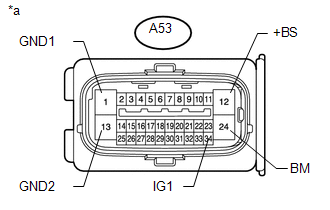
(b) Measure the resistance according to the value(s) in the table below.
Standard Resistance:
|
Tester Connection |
Condition |
Specified Condition |
|---|---|---|
|
A53-1 (GND1) - Body ground |
Always |
Below 1 Ω |
|
A53-13 (GND2) - Body ground |
Always |
Below 1 Ω |
(c) Measure the voltage according to the value(s) in the table below.
Standard Voltage:
|
Tester Connection |
Condition |
Specified Condition |
|---|---|---|
|
A53-12 (+BS) - Body ground |
Always |
11 to 14 V |
|
A53-24 (BM) - Body ground |
Always |
11 to 14 V |
|
A53-34 (IG1) - Body ground |
Ignition switch ON |
11 to 14 V |
|
*a |
Front view of wire harness connector (to Skid Control ECU [Brake Actuator Assembly]) |
| OK | |
REPLACE SKID CONTROL ECU (BRAKE ACTUATOR ASSEMBLY) |
| NG | |
REPAIR OR REPLACE HARNESS OR CONNECTOR |
 Lost Communication with A/C ECU (U0164)
DESCRIPTION
DTC Code
DTC Detection Condition
Trouble Area
U0164
There is no communication from the air conditioning amplifier assembly.
...
 Skid Control ECU Communication Stop Mode
DESCRIPTION
Detection Item
Symptom
Trouble Area
Brake Actuator (Skid Control ECU) Communication Stop Mode
Either condition is met:
...
Other materials about Toyota 4Runner:
Open in Stop Light Switch Circuit (C1425)
DESCRIPTION
The skid control ECU receives the stop light switch assembly signal and detects
the brake pedal operation status.
The skid control ECU has an open detection circuit, which stores this DTC if
it detects an open in the stop light input line of ...
Disabling the TRAC/VSC systems (2WD models)
If the vehicle gets stuck in fresh snow or mud, the TRAC/VSC systems may
reduce power from the engine to the wheels. You may need to turn the system off
to enable you to rock the vehicle in order to free it.
Turning off the TRAC system only (turning on th ...

0.0073