
Toyota 4Runner: Components
COMPONENTS
ILLUSTRATION
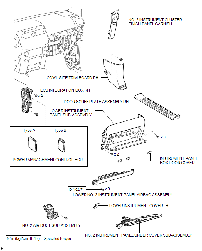

 Removal
REMOVAL
PROCEDURE
1. DISCONNECT CABLE FROM NEGATIVE BATTERY TERMINAL
CAUTION:
Wait at least 90 seconds after disconnecting the cable from the negative (-)
battery terminal to disable the SRS sys ...
Other materials about Toyota 4Runner:
Disassembly
DISASSEMBLY
PROCEDURE
1. REMOVE STEERING LOCK ACTUATOR ASSEMBLY
(a) Using a center punch, mark the center of the tapered-head bolt.
(b) Using a 3 to 4 mm (0.118 to 0.157 in.) drill, drill a hole in the 2 bolts.
(c) Using a screw extractor, remo ...
Removal
REMOVAL
PROCEDURE
1. REMOVE INSTRUMENT PANEL SUB-ASSEMBLY
(a) Remove the instrument panel sub-assembly (See page
).
2. REMOVE NO. 1 HEATER TO REGISTER DUCT
3. REMOVE NO. 2 HEATER TO REGISTER DUCT
4. REMOVE NO. 1 SIDE DEFROSTER NOZZLE DUCT
5. ...
© 2016-2026 | www.to4runner.net

0.0137
0.0137