Toyota 4Runner: Removal
REMOVAL
PROCEDURE
1. DISCONNECT CABLE FROM NEGATIVE BATTERY TERMINAL
CAUTION:
Wait at least 90 seconds after disconnecting the cable from the negative (-) battery terminal to disable the SRS system.
NOTICE:
When disconnecting the cable, some systems need to be initialized after the cable
is reconnected (See page .gif) ).
).
2. REMOVE DOOR SCUFF PLATE ASSEMBLY RH
|
(a) Put protective tape around the door scuff plate. Text in Illustration
|
|
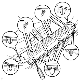
(b) Using a screwdriver, detach the 4 clips, 10 claws and 2 guides and remove the door scuff plate.
HINT:
Tape the screwdriver tip before use.
3. REMOVE COWL SIDE TRIM BOARD RH
|
(a) Remove the clip. |
|
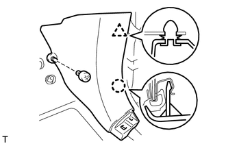
(b) Detach the clip and claw and remove the cowl side trim board.
4. REMOVE NO. 2 INSTRUMENT CLUSTER FINISH PANEL GARNISH
HINT:
Use the same procedure described for the No. 1 instrument cluster finish panel garnish.
(a) Remove the No. 2 instrument cluster finish panel garnish (See page
).
5. REMOVE NO. 2 INSTRUMENT PANEL UNDER COVER SUB-ASSEMBLY
6. REMOVE LOWER INSTRUMENT COVER LH
7. REMOVE LOWER NO. 2 INSTRUMENT PANEL AIRBAG ASSEMBLY
8. REMOVE INSTRUMENT PANEL BOX DOOR COVER
9. REMOVE LOWER INSTRUMENT PANEL SUB-ASSEMBLY
10. REMOVE NO. 2 AIR DUCT SUB-ASSEMBLY
11. REMOVE ECU INTEGRATION BOX RH
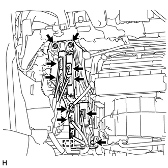
(a) Disconnect all the connectors.
(b) Detach the clamp.
(c) Remove the 2 nuts, bolt and ECU integration box RH.
12. REMOVE POWER MANAGEMENT CONTROL ECU
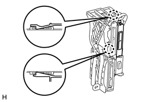
(a) Detach the 2 claws and remove the power management control ECU.
 Components
COMPONENTS
ILLUSTRATION
...
 Installation
INSTALLATION
CAUTION / NOTICE / HINT
HINT:
A bolt without a torque specification is shown in the standard bolt chart (See
page ).
PROCEDURE
1. INSTALL POWER MANAGEMENT CONTROL ECU
(a) Attach ...
Other materials about Toyota 4Runner:
Registration
REGISTRATION
PROCEDURE
1. BEFORE REGISTRATION
NOTICE:
The transmitter ID is written on the tire pressure warning valve and transmitter.
It is not possible to read the transmitter ID after installing the tire onto the
wheel. Therefore, make a note of th ...
Installation
INSTALLATION
CAUTION / NOTICE / HINT
HINT:
A bolt without a torque specification is shown in the standard bolt chart (See
page ).
PROCEDURE
1. INSTALL MULTIPLEX NETWORK BODY ECU
NOTICE:
Make sure that no foreign objects contact the connecting ...

0.026