Toyota 4Runner: Disassembly
DISASSEMBLY
CAUTION / NOTICE / HINT
PROCEDURE
1. REMOVE OUTER MIRROR LH
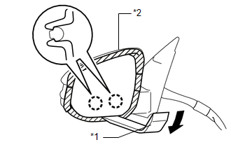
(a) Put protective tape around the outer mirror LH.
|
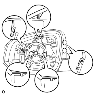
(b) Using a moulding remover, detach the 2 claws of the outer mirror LH as shown in the illustration. Text in Illustration
|
|
|
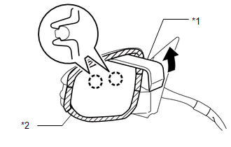
(c) Using a moulding remover, detach the 2 claws of the outer mirror LH as shown in the illustration. Text in Illustration
|
|
|
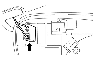
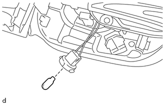
(d) Disconnect the connector and remove the outer mirror LH. |
|
2. REMOVE OUTER MIRROR HOLE COVER LH
|
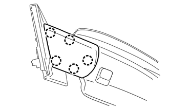
(a) Detach the 5 claws to remove the outer mirror hole cover LH. |
|
3. REMOVE OUTER MIRROR COVER LH
|
(a) Detach the 7 claws to remove the outer mirror cover LH. |
|
4. REMOVE SIDE TURN SIGNAL LIGHT ASSEMBLY LH (w/ Side Turn Signal Light)
.gif)
5. REMOVE OUTER MIRROR LIGHT ASSEMBLY BULB (w/ Side Turn Signal Light)
|
(a) Remove the outer mirror light assembly bulb. |
|
 Removal
REMOVAL
CAUTION / NOTICE / HINT
HINT:
Use the same procedure for both the RH and LH sides.
The procedure listed below is for the LH side.
PROCEDURE
1. REMOVE FRONT DOOR LOWER FR ...
 Inspection
INSPECTION
PROCEDURE
1. INSPECT OUTER REAR VIEW MIRROR ASSEMBLY LH (w/ Side Turn Signal Light)
(a) Apply battery voltage and check the operation of the outer mirror
LH.
OK:
...
Other materials about Toyota 4Runner:
Data List / Active Test
DATA LIST / ACTIVE TEST
1. READ DATA LIST
HINT:
Using the Techstream to read the Data List allows the values or states of switches,
sensors, actuators and other items to be read without removing any parts. This non-intrusive
inspection can be very usefu ...
VSC OFF Indicator Light does not Come ON
DESCRIPTION
Refer to VSC OFF Indicator Light Remains ON (See page
).
WIRING DIAGRAM
Refer to VSC OFF Indicator Light Remains ON (See page
).
CAUTION / NOTICE / HINT
NOTICE:
When replacing the master cylinder solenoid, perform calibration (See page
...

0.0079