Toyota 4Runner: Inspection
INSPECTION
PROCEDURE
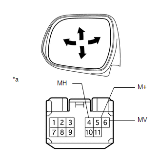
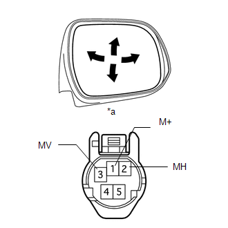
1. INSPECT OUTER REAR VIEW MIRROR ASSEMBLY LH (w/ Side Turn Signal Light)
|
(a) Apply battery voltage and check the operation of the outer mirror LH. OK:
If the result is not as specified, replace the outer rear view mirror assembly LH. |
|
|
(b) Check the outer mirror heater LH. (1) Measure the resistance according to the value(s) in the table below. Standard Resistance:
If the result is not as specified, replace the outer rear view mirror assembly LH. (2) Apply battery voltage to check the operation of the outer mirror heater LH. OK:
HINT: It will take a short amount of time for the outer mirror LH to become warm. If the result is not as specified, replace the outer rear view mirror assembly LH. |
|
(c) Check the side turn signal light assembly LH.
|
(1) Apply battery voltage to the connector to check the illumination condition. OK:
If the result is not as specified, inspect the side turn signal light
assembly LH (See page If the result is not as specified, replace the outer rear view mirror assembly LH. |
|
.gif) ).
).
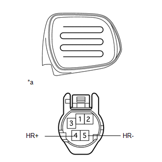
2. INSPECT OUTER REAR VIEW MIRROR ASSEMBLY LH (w/o Side Turn Signal Light)
|
(a) Apply battery voltage to check the operation of the outer mirror LH. OK:
If the result is not as specified, replace the outer rear view mirror assembly LH. |
|
(b) Check the outer mirror heater LH.
|
(1) Measure the resistance according to the value(s) in the table below. Standard Resistance:
If the result is not as specified, replace the outer rear view mirror assembly LH. |
|
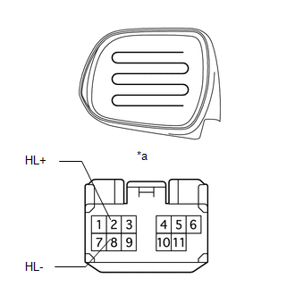
(2) Apply battery voltage to check the operation of the outer mirror heater LH.
OK:
|
Condition |
Specified Condition |
|---|---|
|
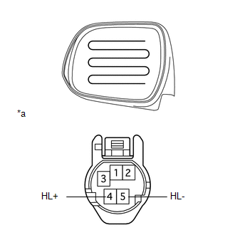
Battery positive (+) → Terminal 4 (HL+) Battery negative (-) → Terminal 5 (HL-) |
Mirror becomes warm |
|
*a |
Component without harness connected (Outer Rear View Mirror Assembly LH) |
HINT:
It will take a short amount of time for the outer mirror LH to become warm.
If the result is not as specified, replace the outer rear view mirror assembly LH.
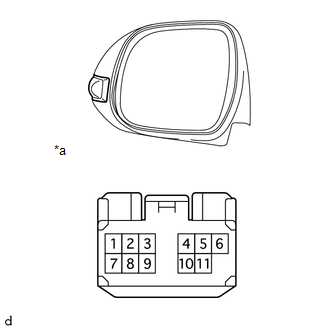
3. INSPECT OUTER REAR VIEW MIRROR ASSEMBLY RH (w/ Side Turn Signal Light)
|
(a) Apply battery voltage to check the operation of the outer mirror RH. OK:
If the result is not as specified, replace the outer rear view mirror assembly RH. |
|
(b) Check the outer mirror heater RH.
|
(1) Measure the resistance according to the value(s) in the table below. Standard Resistance:
If the result is not as specified, replace the outer rear view mirror assembly RH. |
|
(2) Apply battery voltage to check the operation of the outer mirror heater RH.
OK:
|
Condition |
Specified Condition |
|---|---|
|
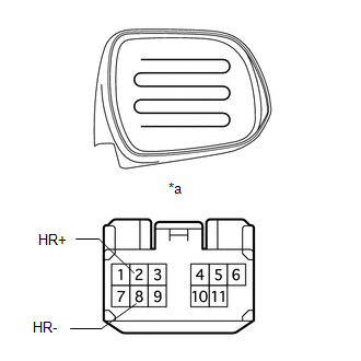
Battery positive (+) → Terminal 2 (HR+) Battery negative (-) → Terminal 8 (HR-) |
Mirror becomes warm |
|
*a |
Component without harness connected (Outer Rear View Mirror Assembly RH) |
HINT:
It will take a short amount of time for the outer mirror RH to become warm.
If the result is not as specified, replace the outer rear view mirror assembly RH.
(c) Check the side turn signal light assembly RH.
|
(1) Apply battery voltage to the connector to check the illumination condition. OK:
If the result is not as specified, inspect the side turn signal light
assembly RH (See page If the result is not as specified, replace the outer rear view mirror assembly RH. |
|
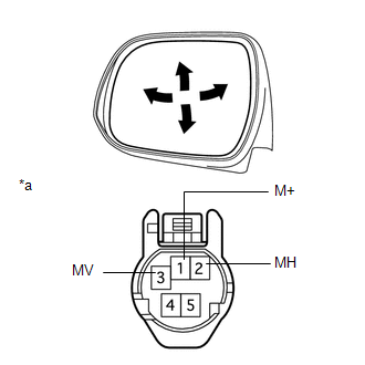
4. INSPECT OUTER REAR VIEW MIRROR ASSEMBLY RH (w/o Side Turn Signal Light)
|
(a) Apply battery voltage to check the operation of the outer mirror. OK:
If the result is not as specified, replace the outer rear view mirror assembly RH. |
|
(b) Check the outer mirror heater RH.
|
(1) Measure the resistance according to the value(s) in the table below. Standard Resistance:
If the result is not as specified, replace the outer rear view mirror assembly RH. |
|
(2) Apply battery voltage to check the operation of the outer mirror heater RH.
OK:
|
Condition |
Specified Condition |
|---|---|
|
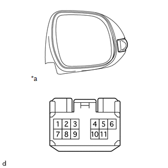
Battery positive (+) → Terminal 4 (HR+) Battery negative (-) → Terminal 5 (HR-) |
Mirror becomes warm |
|
*a |
Component without harness connected (Outer Rear View Mirror Assembly RH) |
HINT:
It will take a short amount of time for the outer mirror RH to become warm.
If the result is not as specified, replace the outer rear view mirror assembly RH.
 Disassembly
DISASSEMBLY
CAUTION / NOTICE / HINT
PROCEDURE
1. REMOVE OUTER MIRROR LH
(a) Put protective tape around the outer mirror LH.
(b) Using a moulding remover, detach the 2 claws of the oute ...
 Reassembly
REASSEMBLY
CAUTION / NOTICE / HINT
HINT:
Use the same procedure for both the RH and LH sides.
The procedure listed below is for the LH side.
PROCEDURE
1. INSTALL OUTER MIRROR LI ...
Other materials about Toyota 4Runner:
Reassembly
REASSEMBLY
PROCEDURE
1. INSTALL FRONT PROPELLER SHAFT UNIVERSAL JOINT SPIDER BEARING
HINT:
Use the same procedure for all propeller shaft universal joint spider bearing.
(a) Apply MP grease to a new spider and spider bearing.
NOTICE:
Be c ...
Components
COMPONENTS
ILLUSTRATION
ILLUSTRATION
ILLUSTRATION
ILLUSTRATION
ILLUSTRATION
...

0.0087