Toyota 4Runner: Disassembly
DISASSEMBLY
PROCEDURE
1. REMOVE COOLER BRACKET
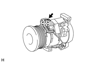
(a) Detach the clamp.
(b) Remove the screw and cooler bracket.
2. REMOVE MAGNET CLUTCH ASSEMBLY
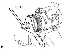
(a) Clamp the cooler compressor in a vise.
(b) Using SST, hold the magnet clutch hub.
SST: 07112-76060
(c) Remove the bolt, magnet clutch hub and magnet clutch washer(s).
HINT:
There is no set number of magnet clutch washers since they are used for adjusting.
|
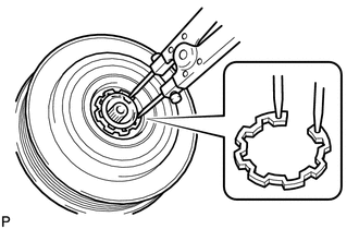
(d) Using a snap ring expander, remove the snap ring and magnet clutch rotor. NOTICE: Do not damage the seal cover of the bearing when removing the snap ring. |
|
(e) Disconnect the connector.
|
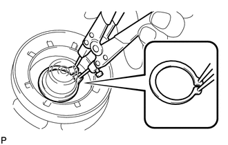
(f) Using a snap ring expander, remove the snap ring and magnet clutch stator. |
|
 Components
COMPONENTS
ILLUSTRATION
ILLUSTRATION
...
 Inspection
INSPECTION
PROCEDURE
1. INSPECT MAGNET CLUTCH ASSEMBLY
(a) Check the magnet clutch operation.
(1) Confirm that the magnet clutch hub and magnet clutch rotor lock when the
positive (+) lead of ...
Other materials about Toyota 4Runner:
Inspection
INSPECTION
PROCEDURE
1. CHECK BRAKE DISC INSIDE DIAMETER
(a) Using a brake drum gauge or equivalent, measure the inside diameter
of the disc.
Standard inside diameter:
210 mm (8.27 in.)
Maximum inside diameter:
211 mm (8.31 in.) ...
Driver Side Power Window Auto Up / Down Function does not Operate with Power
Window Master Switch
DESCRIPTION
If the auto up/down function does not operate, the cause may be one or more of
the following:
The ECU in the power window regulator motor determines that the power
window regulator motor has not been initialized.
The master switc ...

0.011