Toyota 4Runner: Disassembly
DISASSEMBLY
PROCEDURE
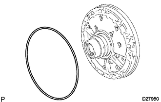
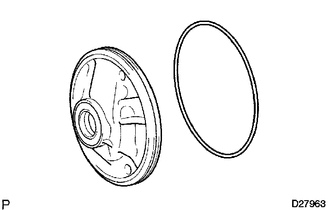
1. REMOVE AUTOMATIC TRANSMISSION CASE O-RING
|
(a) Remove the O-ring from the oil pump assembly. |
|
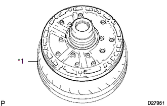
2. FIX OIL PUMP ASSEMBLY
|
(a) Place the oil pump body on the torque converter clutch. Text in Illustration
|
|
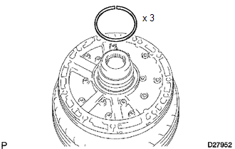
3. REMOVE CLUTCH DRUM OIL SEAL RING
|
(a) Remove the 3 oil seal rings. |
|
4. REMOVE STATOR SHAFT ASSEMBLY
|
(a) Remove the 14 bolts and stator shaft from the oil pump body. |
|
5. REMOVE FRONT OIL PUMP BODY O-RING
|
(a) Remove the O-ring from the oil pump body. |
|
(b) Remove the oil pump body from the torque converter clutch.
6. INSPECT FRONT OIL PUMP BODY SUB-ASSEMBLY
.gif)
7. INSPECT STATOR SHAFT ASSEMBLY
8. INSPECT CLEARANCE OF OIL PUMP ASSEMBLY
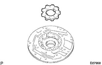
9. REMOVE FRONT OIL PUMP DRIVE GEAR
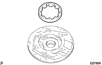
10. REMOVE FRONT OIL PUMP DRIVEN GEAR
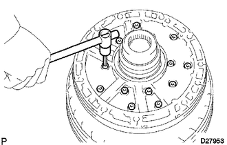
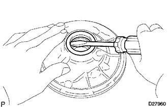
11. REMOVE FRONT OIL PUMP OIL SEAL
|
(a) Using a screwdriver, pry out the oil seal. NOTICE: Be careful not to damage the bushing or oil pump body. |
|
 Components
COMPONENTS
ILLUSTRATION
...
 Inspection
INSPECTION
PROCEDURE
1. INSPECT FRONT OIL PUMP BODY SUB-ASSEMBLY
(a) Using a dial indicator, measure the inside diameter of the oil pump
body bush.
Maximum inside diameter:
38 ...
Other materials about Toyota 4Runner:
Vehicle Speed Signal (C1541)
DESCRIPTION
The power steering ECU assembly receives vehicle speed signals from the master
cylinder solenoid (skid control ECU) via CAN communication. The power steering ECU
assembly provides appropriate assisting force in accordance with the vehicle spee ...
Operation Check
OPERATION CHECK
1. CHECK NAVIGATION SYSTEM NORMAL CONDITION
(a) If the symptom is applicable to any of the following, it is intended behavior,
and not a malfunction.
Symptom
Answer
A longer route than expected is cho ...

0.0072