Toyota 4Runner: Disassembly
DISASSEMBLY
PROCEDURE
1. REMOVE SHIFT LEVER CAP
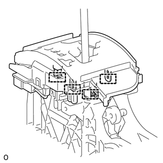
2. REMOVE POSITION INDICATOR HOUSING ASSEMBLY
|
(a) Detach the 4 claws and remove the floor shift position indicator housing. |
|
3. REMOVE INDICATOR LIGHT WIRE SUB-ASSEMBLY
|
(a) Detach the wire connector clamp from the position indicator housing. |
|
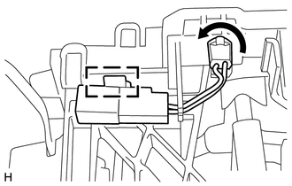
(b) Rotate the indicator light wire socket counterclockwise to align the key part and remove the wire.
|
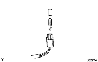
(c) Remove the cap and bulb from the indicator light wire socket. |
|
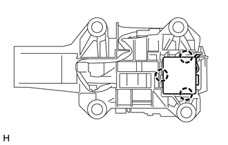
4. REMOVE SHIFT LOCK CONTROL ECU SUB-ASSEMBLY
(a) Disconnect the shift lock solenoid connector from the shift lock control ECU.
|
(b) Detach the 3 claws and remove the shift lock control ECU from the transmission floor shift. |
|
 Removal
REMOVAL
PROCEDURE
1. REMOVE REAR CONSOLE BOX ASSEMBLY
(a) Remove the rear console box (See page ).
2. DISCONNECT TRANSMISSION CONTROL CABLE ASSEMBLY
(a) Move the shift lever to N.
(b ...
 Inspection
INSPECTION
PROCEDURE
1. INSPECT TRANSMISSION CONTROL SWITCH
(a) Measure the resistance according to the value(s) in the table below.
Standard Resistance:
Tester Connection
...
Other materials about Toyota 4Runner:
Transfer Oil
On-vehicle Inspection
ON-VEHICLE INSPECTION
PROCEDURE
1. CHECK TRANSFER OIL
(a) Remove the filler plug and gasket.
(b) Check that the oil level is between 0 to 5.0 mm (0 to 0.196 in.)
f ...
Front Speed Sensor RH Malfunction (C1401,C1271,C1272,C1402)
DESCRIPTION
The speed sensor detects the wheel speed and sends the appropriate signals to
the skid control ECU. These signals are used for brake control.
The speed sensor rotors have rows of alternating N and S magnetic poles and their
magnetic fields ch ...

0.0113