Toyota 4Runner: Disassembly
DISASSEMBLY
CAUTION / NOTICE / HINT
PROCEDURE
1. REMOVE FRONT WHEEL ADJUSTING NUT LH
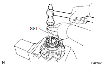
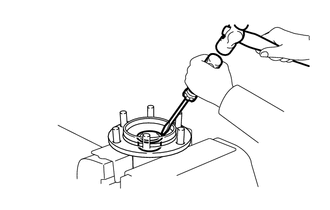
(a) Using SST and a hammer, unstake the adjusting nut.
SST: 09930-00010
|
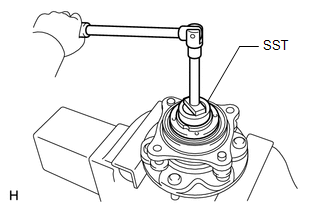
(b) Using SST, remove the adjusting nut. SST: 09318-12010 |
|
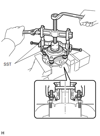
2. REMOVE FRONT AXLE WITH ABS ROTOR BEARING ASSEMBLY LH
(a) Gently fix the front axle hub in a vise between aluminum plates.
NOTICE:
Do not damage the threads of the hub bolts.
|
(b) Using SST, remove the bearing. SST: 09710-30021 09710-03051 SST: 09950-40011 09951-04020 09952-04010 09953-04020 09954-04010 09955-04061 09957-04010 09958-04011 |
|
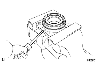
3. REMOVE FRONT AXLE HUB OIL SEAL LH
|
(a) Using a screwdriver, remove the front axle hub oil seal. |
|
4. REMOVE PLUG
|
(a) Using a screwdriver and hammer, remove the plug. |
|
 Removal
REMOVAL
CAUTION / NOTICE / HINT
HINT:
Use the same procedure for the RH and LH sides.
The procedure listed below is for the LH side.
PROCEDURE
1. REMOVE FRONT WHEEL
2. REMOVE D ...
 Reassembly
REASSEMBLY
CAUTION / NOTICE / HINT
PROCEDURE
1. INSTALL PLUG
(a) Using the SST and a hammer, install a new plug.
SST: 09950-60010
09951-00450
SST: 09950-70010
09951-07100
...
Other materials about Toyota 4Runner:
Terminals Of Ecu
TERMINALS OF ECU
1. CHECK NO. 1 AIR CONDITIONING AMPLIFIER ASSEMBLY
(a) Disconnect the F42 No. 1 air conditioning amplifier assembly connector.
(b) Measure the voltage and resistance according to the value(s) in the table
below.
Terminal No. ...
Diagnostic Trouble Code Chart
DIAGNOSTIC TROUBLE CODE CHART
HINT:
If a trouble code is output during the DTC check, inspect the trouble areas listed
for that code. For details of the code, refer to the "See page" below.
Sliding Roof System
DTC Code
Det ...

0.0068