Toyota 4Runner: Disassembly
DISASSEMBLY
PROCEDURE
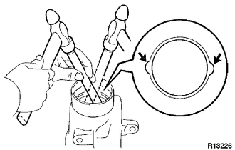
1. INSPECT DIFFERENTIAL RING GEAR BACKLASH
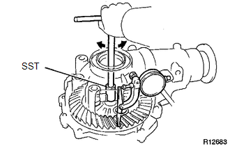
(a) Using SST and a dial indicator, measure the ring gear backlash.
SST: 09564-32011
Standard backlash:
0.11 to 0.21 mm (0.00433 to 0.00827 in.)
If the backlash is not as specified, adjust the side bearing preload or perform repairs as necessary.
HINT:
Perform the measurement at 3 or more positions around the circumference of the ring gear.
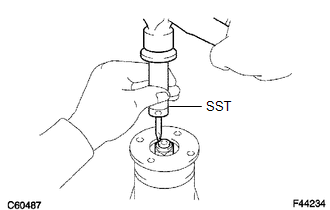
2. INSPECT FRONT DRIVE PINION COMPANIONFLANGE SUB-ASSEMBLY
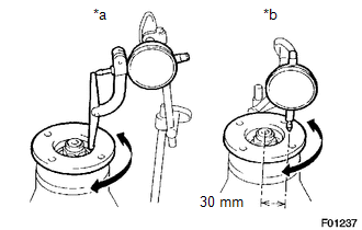
(a) Using a dial indicator, measure the runout of the companion flange vertically and laterally.
Distance from center to runout measurement point:
30 mm (1.18 in.)
Maximum Runout:
|
Item |
Specified Condition |
|---|---|
|
Vertical runout |
0.10 mm (0.00394 in.) |
|
Lateral runout |
0.10 mm (0.00394 in.) |
|
*a |
Vertical Runout |
|
*b |
Lateral Runout |
If the runout is more than the maximum, replace the companion flange.
3. REMOVE DIFFERENTIAL VACUUM ACTUATOR ASSEMBLY (w/ A.D.D.)
|
(a) Remove the 4 bolts. |
|
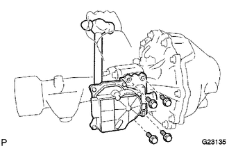
(b) Using a hammer handle, pry out the actuator from the differential tube.
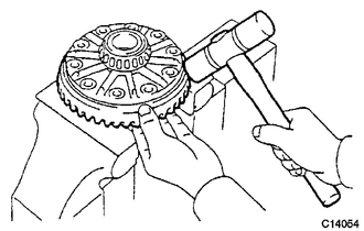
4. REMOVE FRONT DIFFERENTIAL TUBE ASSEMBLY
|
(a) Using an E14 "TORX" socket wrench, remove the 4 bolts. |
|
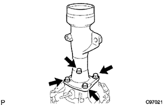
(b) Using a plastic-faced hammer, tap out the differential tube.
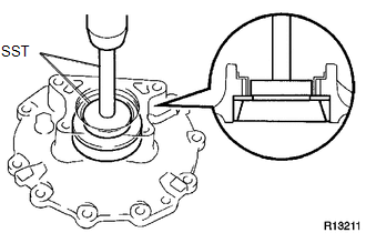
5. REMOVE DIFFERENTIAL SIDE GEAR SHAFT OIL SEAL
|
(a) Using SST, remove the 2 oil seals. SST: 09308-00010 |
|
6. REMOVE DIFFERENTIAL SIDE GEAR INTER SHAFT SUB-ASSEMBLY (w/ A.D.D.)
|
(a) Using SST, remove the side gear inter shaft. SST: 09350-20015 09369-20040 SST: 09950-40011 09951-04010 09952-04010 09953-04020 09954-04010 09955-04011 09957-04010 09958-04011 |
|
(b) Remove the snap ring from the side gear inter shaft.
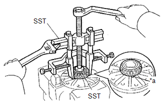
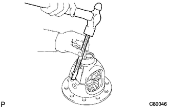
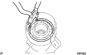
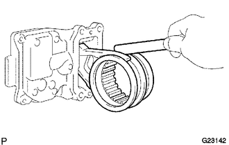
7. REMOVE FRONT DIFFERENTIAL SIDE BEARING RETAINER DEFLECTOR (w/ A.D.D.)
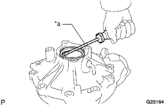
(a) Using a screwdriver pry out the bearing retainer deflector.
HINT:
Tape the screwdriver tip before use.
Text in Illustration|
*a |
Protective Tape |
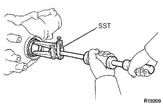
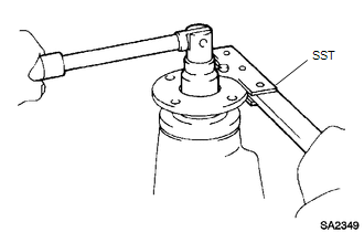
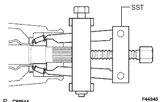
8. REMOVE FRONT DRIVE PINION COMPANION FLANGE NUT
(a) Using SST and a hammer, unstake the nut.
SST: 09930-00010
|
(b) Using SST to hold the companion flange, remove the nut. SST: 09330-00021 |
|
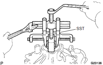
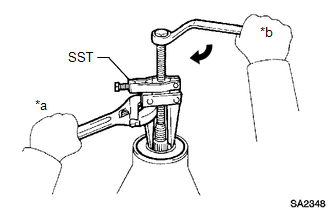
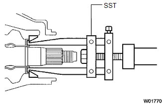
9. REMOVE FRONT DRIVE PINION COMPANION FLANGE SUB-ASSEMBLY
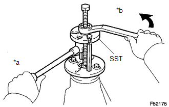
(a) Using SST, remove the companion flange.
SST: 09950-30012
09951-03010
09953-03010
09954-03010
09955-03030
09956-03020
Text in Illustration|
*a |
Hold |
|
*b |
Turn |
NOTICE:
Before using SST (center bolt), apply hypoid gear oil to its threads and tip.
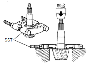
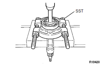
10. REMOVE FRONT DIFFERENTIAL DUST DEFLECTOR
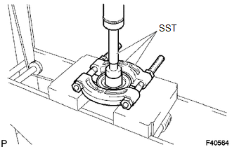
(a) Using SST and a press, press out the dust deflector.
SST: 09950-00020
SST: 09950-60010
09951-00510
SST: 09950-70010
09951-07150
NOTICE:
Do not drop the companion flange.
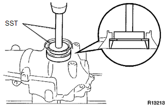
11. REMOVE FRONT DIFFERENTIAL CARRIER OIL SEAL
|
(a) Using SST, remove the oil seal from the differential carrier assembly. SST: 09308-10010 Text in Illustration
|
|
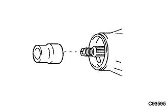
12. REMOVE FRONT DIFFERENTIAL DRIVE PINION OIL SLINGER
(a) Remove the oil slinger from the drive pinion.
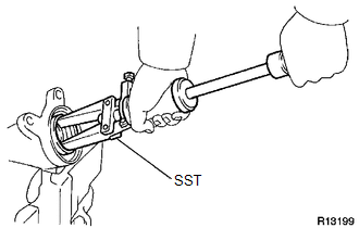
13. REMOVE FRONT DRIVE PINION FRONT TAPERED ROLLER BEARING (INNER)
|
(a) Using SST, remove the front tapered roller bearing (inner) from the drive pinion. SST: 09556-22010 |
|
14. REMOVE FRONT DRIVE PINION FRONT TAPERED ROLLER BEARING (OUTER)
|
(a) Using SST, remove the front tapered roller bearing (outer). SST: 09308-00010 |
|
15. REMOVE FRONT DIFFERENTIAL OIL STORAGE RING
(a) Using a screwdriver and hammer, tap out the oil storage ring.
16. REMOVE FRONT DIFFERENTIAL DRIVE PINION BEARING SPACER
(a) Remove the bearing spacer.
17. REMOVE DIFFERENTIAL SIDE BEARING RETAINER
(a) Using a screwdriver, remove the union.
(b) Remove the 10 bolts and tap out the side bearing retainer with a plastic-faced hammer.
18. REMOVE DIFFERENTIAL CASE ASSEMBLY
19. REMOVE DIFFERENTIAL DRIVE PINION
20. REMOVE FRONT DRIVE PINION REAR TAPERED ROLLER BEARING (INNER)
|
(a) Using SST and a press, remove the rear tapered roller bearing (inner) and washer from the drive pinion. SST: 09950-00020 NOTICE: Do not drop the drive pinion. HINT: If the drive gear or ring gear is damaged, replace them as a set. |
|
21. REMOVE FRONT DRIVE PINION REAR TAPERED ROLLER BEARING (OUTER)
|
(a) Using a brass bar and hammer, remove the rear tapered roller bearing (outer). |
|
22. REMOVE FRONT DIFFERENTIAL CASE BEARING
HINT:
- Measure the thickness of the case washer.
- Tag the bearing outer races so that they can be reinstalled in the correct locations.
(a) Using SST and a press, press out the case bearing (outer race) and case washer from the bearing retainer.
SST: 09950-60020
09951-00680
SST: 09950-70010
09951-07150
If the bearing is damaged during removal, replace it.
|
(b) Using SST and a press, press out the case bearing (outer race) and plate washer from the differential carrier. SST: 09950-60020 09951-00680 SST: 09950-70010 09951-07150 If the bearing is damaged during removal, replace it. |
|
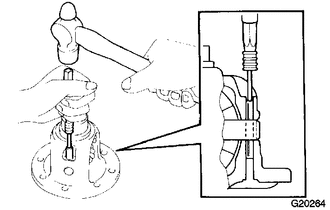
23. REMOVE DIFFERENTIAL RING GEAR
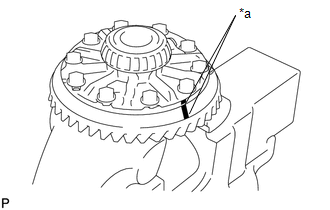
(a) Place matchmarks on the ring gear and differential case.
Text in Illustration|
*a |
Matchmark |
(b) Remove the 10 ring gear set bolts.
|
(c) Using a plastic-faced hammer, tap on the ring gear to separate it from the differential case. |
|
24. REMOVE FRONT DIFFERENTIAL CASE BEARING
HINT:
The differential case and case bearings should only be removed when replacement is necessary.
|
(a) Using SST, remove the 2 differential case bearings (inner) from the differential case. SST: 09950-60010 09951-00390 SST: 09950-40011 09951-04020 09952-04010 09953-04030 09954-04010 09955-04061 09957-04010 09958-04011 Text in Illustration
HINT: Set the claws of SST into the notches in the differential case. |
|
25. REMOVE DIFFERENTIAL CASE ASSEMBLY
|
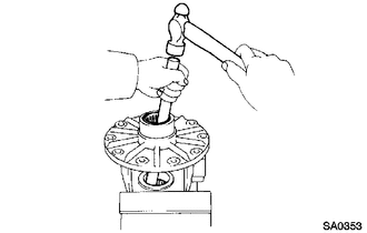
(a) Using a chisel and hammer, unstake the differential case. |
|
|
(b) Using a 5 mm pin punch and hammer, tap out the straight pin. |
|
|
(c) Remove the parts shown in the illustration from the differential case. Text in Illustration
|
|
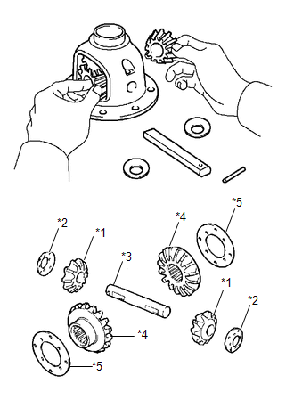
26. INSPECT DIFFERENTIAL GEAR KIT
(a) Check that the differential pinion and differential side gear are not damaged.
If the differential pinion or differential side gear is damaged, replace the differential gear kit.
27. INSPECT FRONT DIFFERENTIAL CASE
(a) Check that the differential case is not damaged.
If the differential case is damaged, replace it.
28. REMOVE FRONT DIFFERENTIAL SIDE GEAR NEEDLE ROLLER BEARING (w/ A.D.D.)
|
(a) Using a brass bar and hammer, tap out the 2 bearings. |
|
29. REMOVE DIFFERENTIAL CLUTCH HUB (w/ A.D.D.)
|
(a) Using a snap ring expander, remove the snap ring. |
|
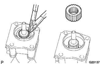
(b) Remove the differential clutch hub.
30. REMOVE DIFFERENTIAL SIDE GEAR SHAFT OIL SEAL
|
(a) Using SST, tap out the oil seal from the differential tube. SST: 09308-00010 |
|
31. REMOVE DIFFERENTIAL SIDE GEAR SHAFT SUB-ASSEMBLY RH
|
(a) Using a snap ring expander, remove the snap ring. |
|
(b) Remove the side gear shaft from the differential tube.
32. REMOVE FRONT DIFFERENTIAL SIDE GEAR SHAFT BEARING RH
|
(a) Using a snap ring expander, remove the snap ring. |
|
(b) Using SST, a brass bar and press, press out the bearing.
SST: 09950-00020
NOTICE:
- Do not damage the bearing.
- Do not drop the shaft.
33. INSPECT DIFFERENTIAL CLUTCH SLEEVE AND DIFFERENTIAL CLUTCH HUB (w/ A.D.D.)
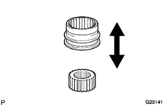
(a) Check that there is no wear or damage to the clutch hub and clutch sleeve.
Replace parts as necessary.
(b) Check that the clutch sleeve slides smoothly on the clutch hub.
Replace parts as necessary.
34. INSPECT DIFFERENTIAL CLUTCH SLEEVE AND DIFFERENTIAL SIDE GEAR INTER SHAFT (w/ A.D.D.)
|
(a) Check for wear and damage to the clutch hub and side gear inter shaft. Replace parts as necessary. |
|
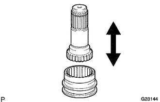
(b) Check that the clutch sleeve slides smoothly on the side gear inter shaft.
Replace parts as necessary.
35. INSPECT DIFFERENTIAL CLUTCH SLEEVE AND CLUTCH SLEEVE FORK CLEARANCE (w/ A.D.D.)
|
(a) Using a feeler gauge, measure the clearance between the sleeve fork and clutch sleeve. Maximum clearance: 0.15 to 0.35 mm (0.00591 to 0.0138 in.) If the clearance is more than the maximum, replace the fork or clutch sleeve. |
|
 Removal
REMOVAL
PROCEDURE
1. DISCONNECT CABLE FROM NEGATIVE BATTERY TERMINAL
NOTICE:
When disconnecting the cable, some systems need to be initialized after the cable
is reconnected (See page ).
2. RE ...
 Reassembly
REASSEMBLY
PROCEDURE
1. INSTALL FRONT DIFFERENTIAL SIDE GEAR SHAFT BEARING RH
(a) Using SST and a press, press in the shaft bearing.
SST: 09223-00010
(b) Using a snap ring expander, install the ...
Other materials about Toyota 4Runner:
Registered Device cannot be Deleted
PROCEDURE
1.
DELETE OPERATION
(a) Check if a registered portable player can be deleted normally.
OK:
Registered portable player can be deleted normally.
OK
USE SIMULATION METHOD TO CHECK
...
Rear Power Window LH does not Operate with Rear Power Window Switch LH
DESCRIPTION
If the manual up/down function does not operate, there may be a malfunction
in the rear power window regulator switch, rear power window regulator motor,
harness or connector.
WIRING DIAGRAM
CAUTION / NOTICE / HINT
NOTICE ...

0.0156