
Toyota 4Runner: Removal
REMOVAL
PROCEDURE
1. DISCONNECT CABLE FROM NEGATIVE BATTERY TERMINAL
NOTICE:
When disconnecting the cable, some systems need to be initialized after the cable
is reconnected (See page .gif) ).
).
2. REMOVE FRONT WHEELS
3. REMOVE NO. 1 ENGINE UNDER COVER SUB-ASSEMBLY
(a) Remove the No. 1 engine under cover (See page
).
4. REMOVE REAR ENGINE UNDER COVER ASSEMBLY
(a) Remove the rear engine under cover (See page
).
5. DRAIN DIFFERENTIAL OIL
6. REMOVE FRONT PROPELLER SHAFT ASSEMBLY
(a) Remove the front propeller shaft (See page
).
7. REMOVE FRONT DRIVE SHAFT ASSEMBLY
(a) Remove the front drive shaft (See page ).
8. REMOVE FRONT STABILIZER LINK ASSEMBLY
(a) Remove the stabilizer link (See page ).
9. REMOVE FRONT SPEED SENSOR
(a) Remove the front speed sensor (See page
).
10. DISCONNECT TIE ROD END SUB-ASSEMBLY LH
(a) Disconnect the tie rod end sub-assembly (See page
).
11. DISCONNECT TIE ROD END SUB-ASSEMBLY RH
(a) Disconnect the tie rod end sub-assembly (See page
).
12. REMOVE FRONT LOWER NO. 1 SUSPENSION ARM SUB-ASSEMBLY LH
(a) Remove the front lower No. 1 suspension arm sub-assembly (See page
).
13. REMOVE FRONT LOWER NO. 1 SUSPENSION ARM SUB-ASSEMBLY RH
HINT:
Use the same procedure described for the LH side.
14. REMOVE FRONT DIFFERENTIAL CARRIER ASSEMBLY
.png)
(a) Remove the bolt and disconnect the front differential breather tube bracket.
(b) Support the front differential with a jack.
(c) Remove the front No. 1 differential mount nut.
(d) Remove the 2 front mounting bolts and nut.
Text in Illustration|
*1 |
Mounting Bolt |
|
*2 |
Mounting Nut |
(e) for w/A.D.D. :
Disconnect the actuator hose and connector.
(f) Lower the jack and remove the front differential.
|
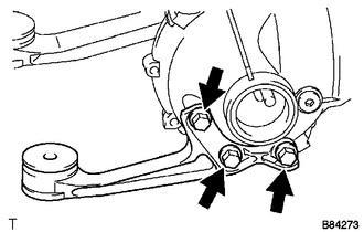
(g) Remove the 3 bolts and front No. 1 differential support. |
|
|
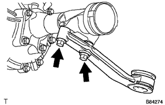
(h) Remove the 2 bolts and front No. 2 differential support. |
|
|
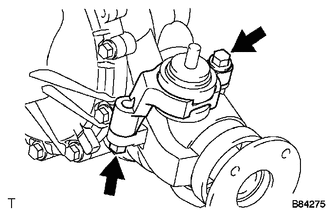
(i) Remove the 2 bolts and front No. 3 differential support. |
|
 Components
COMPONENTS
ILLUSTRATION
ILLUSTRATION
ILLUSTRATION
ILLUSTRATION
...
 Disassembly
DISASSEMBLY
PROCEDURE
1. INSPECT DIFFERENTIAL RING GEAR BACKLASH
(a) Using SST and a dial indicator, measure the ring gear backlash.
SST: 09564-32011
Standard backlash:
0.11 to 0.21 mm (0.004 ...
Other materials about Toyota 4Runner:
Inspection
INSPECTION
PROCEDURE
1. INSPECT NAVIGATION ANTENNA ASSEMBLY
(a) Measure the resistance according to the value(s) in the table below.
Standard Resistance:
Tester Connection
Condition
Specif ...
System Description
SYSTEM DESCRIPTION
1. KEY REMINDER WARNING SYSTEM DESCRIPTION
(a) When the driver side door is opened while the ignition switch is ACC or off
and the key is in the ignition key cylinder, this system causes a buzzer to sound
in order to warn the driver th ...

0.0268