Toyota 4Runner: Disassembly
DISASSEMBLY
PROCEDURE
1. FIX REAR DIFFERENTIAL CARRIER ASSEMBLY IN PLACE
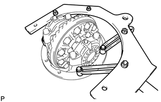
(a) Fix the rear differential carrier assembly to the overhaul attachment.
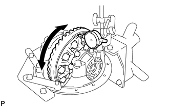
2. INSPECT REAR DRIVE PINION COMPANION FLANGE SUB-ASSEMBLY REAR
.png)
(a) Using a dial indicator, measure the runout of the companion flange vertically and laterally.
Distance from center to runout measurement point:
30 mm (1.18 in.)
Maximum Runout:
|
Item |
Specified Condition |
|---|---|
|
Vertical runout |
0.10 mm (0.00394 in.) |
|
Lateral runout |
0.10 mm (0.00394 in.) |
|
*a |
Vertical Runout |
|
*b |
Lateral Runout |
If the runout is more than the maximum, replace the companion flange.
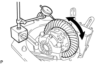
3. INSPECT RUNOUT OF DIFFERENTIAL RING GEAR
(a) Using a dial indicator, check the runout of the ring gear.
Maximum runout:
0.07 mm (0.00276 in.)
If the runout is more than the maximum, replace the ring gear with a new one.
4. INSPECT DIFFERENTIAL RING GEAR BACKLASH
(a) Using a dial indicator, check the backlash of the ring gear.
Standard backlash:
0.10 to 0.20 mm (0.00394 to 0.00787 in.)
If the backlash is not within the specification, adjust the side bearing preload or performs repairs as necessary.
5. INSPECT DIFFERENTIAL DRIVE PINION PRELOAD
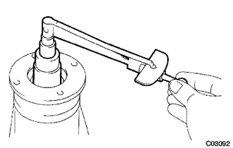
(a) Using a torque wrench, measure the preload of the backlash between the drive pinion and ring gear.
Standard preload (at starting):
0.88 to 1.98 N*m (8.97 to 20.2 kgf*cm, 7.79 to 17.5 in.*lbf)
If necessary, disassemble and inspect the differential assembly.
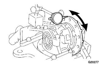
6. INSPECT TOTAL PRELOAD
(a) Using a torque wrench, measure the preload with the teeth of the drive pinion and ring gear in contact.
(b) Using a torque wrench, measure the total preload.
Standard total preload (at starting):
Drive pinion preload plus 0.20 to 0.40 N*m (2.0 to 4.1 kgf*cm, 1.8 to 3.5 in.*lbf)
If necessary, disassemble and inspect the differential.
7. REMOVE DIFFERENTIAL LOCK SHIFT ACTUATOR
(a) Remove the 4 bolts and actuator from the differential carrier.
(b) Remove the O-ring.
8. REMOVE DIFFERENTIAL LOCK INDICATOR SWITCH
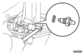
(a) Remove the indicator switch and gasket.
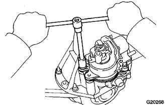
9. REMOVE REAR DIFFERENTIAL LOCK SHIFT FORK SHAFT
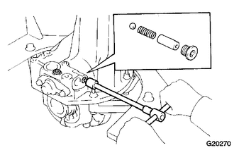
(a) Using a 6 mm hexagon wrench, remove the 2 screw plugs.
(b) Remove the spring seat, spring and ball.
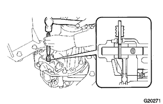
|
(c) Using a 5 mm pin punch and hammer, remove the slotted pin. |
|
|
(d) Remove the 2 bolts from the shaft retainer. |
|
(e) Using a plastic-faced hammer, remove the shaft retainer.
(f) Remove the shift fork shaft.
(g) Remove the rear differential lock sleeve.
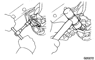
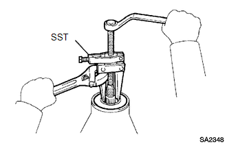
10. REMOVE REAR DRIVE PINION NUT
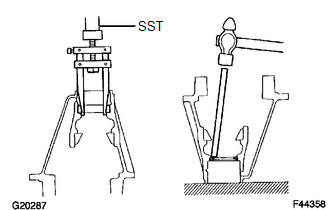
(a) Using SST and a hammer, loosen the staked part of the nut.
SST: 09930-00010
NOTICE:
- Be sure to use SST with the tapered surface facing the shaft.
- Do not grind the tip of the SST with a grinder, etc.
- Completely loosen the staked part of the nut when removing.
- Do not damage the threads of the drive pinion.
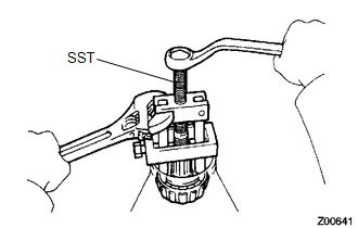
|
(b) Use SST to hold the drive pinion companion flange. SST: 09330-00021 |
|
(c) Using a 30 mm socket wrench, remove the rear drive pinion nut.
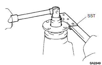
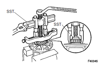
11. REMOVE REAR DRIVE PINION COMPANION FLANGE SUB-ASSEMBLY REAR
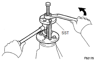
(a) Using SST, remove the drive pinion companion flange.
SST: 09950-30012
09951-03010
09953-03010
09954-03010
09955-03030
09956-03040
NOTICE:
Apply grease to the threads and tip of the SST center bolt before use.
12. REMOVE REAR DIFFERENTIAL CARRIER OIL SEAL
(a) Using SST, remove the oil seal from the differential carrier.
SST: 09308-10010
13. REMOVE REAR DIFFERENTIAL DRIVE PINION OIL SLINGER
NOTICE:
Apply grease to the threads and tip of the SST center bolt before use.
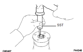
14. REMOVE REAR DRIVE PINION FRONT BEARING (INNER)
(a) Using SST, remove the drive pinion tapered roller bearing from the drive pinion.
SST: 09556-22010
NOTICE:
Apply grease to the threads and tip of the SST center bolt before use.
15. REMOVE REAR DIFFERENTIAL BEARING ADJUSTING NUT LOCK
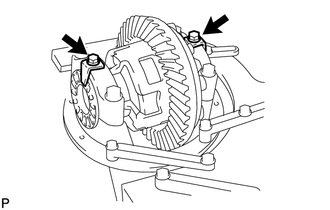
(a) Remove the 2 bolts and 2 rear differential bearing adjusting nut locks.
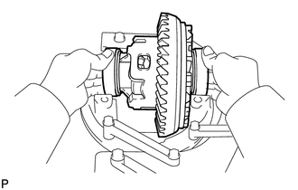
16. REMOVE DIFFERENTIAL CASE ASSEMBLY
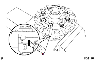
(a) Place matchmarks on the bearing cap and differential carrier.
Text in Illustration|
*a |
Matchmark |
(b) Remove the 4 bolts and 2 differential bearing caps.
(c) Remove the 2 adjusting nuts.
|
(d) Remove the rear differential case sub-assembly and 2 case bearings from the differential carrier. HINT: Tag the 2 case bearing outer races so that they can be reinstalled in the correct locations. |
|
17. REMOVE DIFFERENTIAL DRIVE PINION
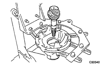
(a) Remove the differential drive pinion and bearing spacer from the differential carrier.
18. REMOVE REAR DRIVE PINION REAR BEARING (INNER)
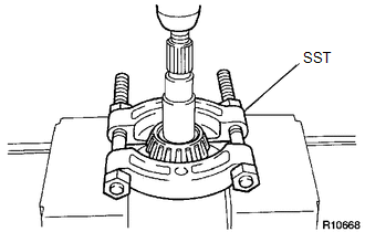
(a) Using SST and a press, remove the drive pinion tapered roller bearing from the drive pinion.
SST: 09950-00020
NOTICE:
Do not drop the drive pinion.
HINT:
If either the drive pinion or ring gear is damaged, replace them as a set.
19. REMOVE REAR DRIVE PINION REAR BEARING (OUTER)
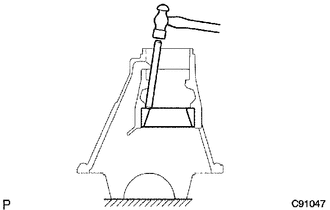
(a) Using a brass bar and hammer, remove the rear tapered roller bearing from the carrier.
HINT:
If the bearing is damaged during the removal, replace it.
20. REMOVE REAR DIFFERENTIAL DRIVE PINION PLATE WASHER
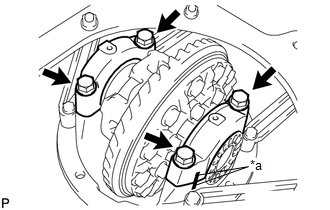
21. REMOVE DIFFERENTIAL RING GEAR
(a) Place matchmarks on the ring gear and differential case.
Text in Illustration|
*a |
Matchmark |
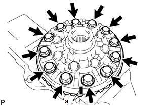
(b) Using a screwdriver and hammer, unstake the lock plates.
(c) Remove the 12 ring gear set bolts.
|
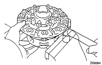
(d) Using a plastic-faced hammer, tap on the ring gear to separate it from the differential case. |
|
.png)
22. REMOVE REAR DRIVE PINION FRONT BEARING (OUTER)
(a) Using SST, remove the front tapered roller bearing from the carrier.
SST: 09308-00010
(b) Using a brass bar and hammer, remove the oil storage ring from the carrier.
HINT:
If the bearing is damaged during the removal, replace it.
23. INSPECT DIFFERENTIAL CASE ASSEMBLY RUNOUT
(a) Install the rear differential case bearing to the differential case.
(b) Install the differential case to the differential carrier.
(c) Install the 2 bearing caps to the differential carrier with the 4 bolts.
Torque:
103 N·m {1050 kgf·cm, 76 ft·lbf}
(d) Inspect the differential case runout.
Maximum runout:
0.07 mm (0.00276 in.)
(e) Remove the differential case.
(f) Remove the rear differential case bearing.
24. REMOVE REAR DIFFERENTIAL CASE BEARING
(a) Using SST, remove the 2 rear differential case bearings from the differential case.
SST: 09950-40011
09953-04020
09951-04010
09952-04010
09954-04010
09955-04061
09957-04010
09958-04011
SST: 09950-60010
09951-00500
09951-00650
09952-06010
25. DISASSEMBLE DIFFERENTIAL CASE
(a) Place matchmarks on the LH and RH cases.
Text in Illustration|
*a |
Matchmark |
(b) Remove the 8 bolts.
|
(c) Using a plastic-faced hammer, separate the LH and RH cases. |
|
|
(d) Remove the parts shown in the illustration from the differential case. Text in Illustration
|
|
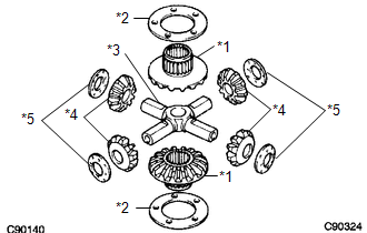
 Removal
REMOVAL
PROCEDURE
1. REMOVE REAR AXLE SHAFT LH
(a) Remove the rear axle shaft LH (See page
).
2. REMOVE REAR AXLE SHAFT RH
HINT:
Use the same procedure described for the LH side.
3. REMOVE P ...
 Inspection
INSPECTION
PROCEDURE
1. INSPECT REAR DIFFERENTIAL LOCK SLEEVE
(a) Install the sleeve to the differential case (LH) and check that it moves
smoothly.
(b) Install the side gear to the sleeve and ...
Other materials about Toyota 4Runner:
Types of child restraints
Child restraint systems are classified into the following 3 types according
to the age and size of the child:
Rear facing — Infant seat/convertible seat
Forward facing — Convertible seat
Booster seat
Selecting an appropriate child restraint sys ...
Portable Player cannot be Connected Manually/Automatically
CAUTION / NOTICE / HINT
HINT:
Some versions of "Bluetooth" compatible audio players may not function, or the
function may be limited using the radio and display receiver assembly, even if the
portable audio player itself can play files (See pag ...

0.008