Toyota 4Runner: Removal
REMOVAL
PROCEDURE
1. REMOVE REAR AXLE SHAFT LH
(a) Remove the rear axle shaft LH (See page .gif)
).
2. REMOVE REAR AXLE SHAFT RH
HINT:
Use the same procedure described for the LH side.
3. REMOVE PROPELLER SHAFT ASSEMBLY
(a) Remove the propeller shaft assembly (See page
).
4. REMOVE REAR DIFFERENTIAL CARRIER ASSEMBLY
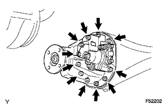
(a) Remove the 11 nuts and 11 washers, differential carrier.
NOTICE:
Be careful not to damage the contact surface.
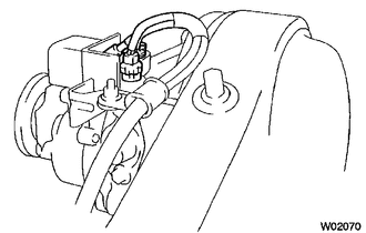
(b) Disconnect the rear differential lock actuator breather hose from the differential actuator assembly.
|
(c) Disconnect the differential lock actuator connector. |
|
5. REMOVE REAR DIFFERENTIAL CARRIER GASKET
 Components
COMPONENTS
ILLUSTRATION
ILLUSTRATION
ILLUSTRATION
...
 Disassembly
DISASSEMBLY
PROCEDURE
1. FIX REAR DIFFERENTIAL CARRIER ASSEMBLY IN PLACE
(a) Fix the rear differential carrier assembly to the overhaul attachment.
2. INSPECT REAR DRIVE PINION COMPANION FLANGE ...
Other materials about Toyota 4Runner:
Operation Check
OPERATION CHECK
1. CHECK FRONT POWER SEAT FUNCTION
(a) Check the basic functions.
Text in Illustration
*a
Sliding Function
*b
Front Vertical Function
*c
Lifter Function
...
Disassembly
DISASSEMBLY
PROCEDURE
1. REMOVE NO. 3 FLOOR WIRE
(a) Disconnect the 4 connectors and remove the 3 pieces of tape.
(b) Detach the 4 clamps to remove the No. 3 floor wire.
2. REMOVE REAR BUMPER SIDE BRACKET LH
(a) Remove the clip and 2 screws. ...

0.0067