Toyota 4Runner: Disassembly
DISASSEMBLY
PROCEDURE
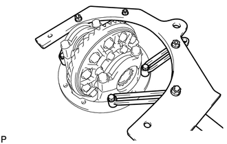
1. FIX REAR DIFFERENTIAL CARRIER ASSEMBLY IN PLACE
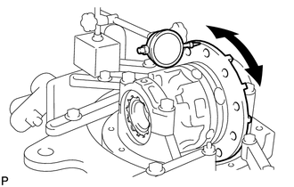
2. INSPECT RUNOUT OF REAR DRIVE PINION COMPANION FLANGE SUB-ASSEMBLY REAR
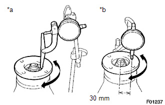
(a) Using a dial indicator, measure the runout of the companion flange vertically and laterally.
Distance from center to runout measurement point:
30 mm (1.18 in.)
Maximum Runout:
|
Item |
Specified Condition |
|---|---|
|
Vertical runout |
0.10 mm (0.00394 in.) |
|
Lateral runout |
0.10 mm (0.00394 in.) |
|
*a |
Vertical Runout |
|
*b |
Lateral Runout |
- If the runout is more than the maximum, replace the companion flange.
3. INSPECT RUNOUT OF DIFFERENTIAL RING GEAR
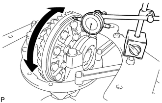
(a) Using a dial indicator, check the runout of the ring gear.
Maximum runout:
0.07 mm (0.00276 in.)
- If the runout is more than the maximum, replace the ring gear with a new one.
4. INSPECT DIFFERENTIAL RING GEAR BACKLASH
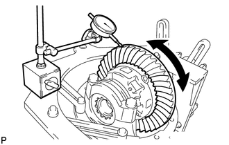
(a) Using a dial indicator, check the backlash of the ring gear.
Standard backlash:
0.10 to 0.20 mm (0.00394 to 0.00787 in.)
- If the backlash is not within the specification, adjust the side bearing
preload or perform repairs as necessary.
HINT:
Perform the measurement at 3 or more positions around the circumference of the ring gear.
5. INSPECT DIFFERENTIAL DRIVE PINION PRELOAD
.png)
(a) Using a torque wrench, measure the preload of the backlash between the drive pinion and ring gear.
Standard preload (at starting):
0.88 to 1.98 N*m (8.97 to 20.2 kgf*cm, 7.79 to 17.5 in.*lbf)
If necessary, disassemble and inspect the differential.
6. INSPECT TOTAL PRELOAD
(a) Using a torque wrench, measure the preload with the teeth of the drive pinion and ring gear in contact.
(b) Using a torque wrench, measure the total preload.
Standard total preload (at starting):
Drive pinion preload plus 1.08 to 2.38 N*m (11.0 to 24.3 kgf*cm, 9.6 to 21.0 in.*lbf)
If necessary, disassemble and inspect the differential.
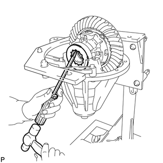
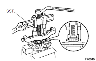
7. REMOVE REAR DRIVE PINION NUT
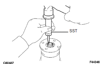
(a) Using SST and a hammer, loosen the staked part of the rear drive pinion nut.
SST: 09930-00010
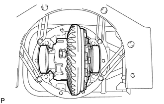
|
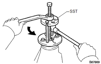
(b) Use SST to hold the companion flange. SST: 09330-00021 |
|
.png)
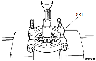
(c) Using a 30 mm socket wrench, remove the rear drive pinion nut.
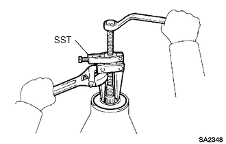
8. REMOVE REAR DRIVE PINION COMPANION FLANGE SUB-ASSEMBLY
(a) Using SST, remove the rear drive pinion companion flange sub-assembly.
SST: 09950-30012
09951-03010
09953-03010
09954-03010
09955-03030
09956-03040
NOTICE:
Before using SST (center bolt), apply hypoid gear oil to its threads and tip.
9. REMOVE REAR DIFFERENTIAL CARRIER OIL SEAL
(a) Using SST, remove the rear differential carrier oil seal from the differential carrier.
SST: 09308-10010
10. REMOVE REAR DIFFERENTIAL DRIVE PINION OIL SLINGER
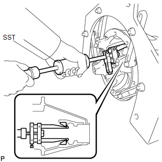
11. REMOVE REAR DRIVE PINION FRONT BEARING (INNER)
.png)
(a) Using SST, remove the rear drive pinion front tapered roller bearing (inner) from the drive pinion.
SST: 09556-22010
12. REMOVE DIFFERENTIAL CASE ASSEMBLY
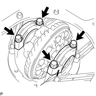
(a) Place matchmarks on the bearing cap and differential carrier.
Text in Illustration|
*1 |
Matchmark |
(b) Remove the 4 bolts and 2 differential bearing caps.
|
(c) Using a screwdriver and hammer, remove the 2 plate washers. HINT: Measure the plate washer thickness and note it down. |
|
|
(d) Remove the rear differential case assembly from the differential carrier. HINT: Tag the 2 case bearing outer races so that they can be reinstalled in the correct locations. |
|
13. REMOVE DIFFERENTIAL DRIVE PINION
|
(a) Remove the drive pinion and bearing spacer from the differential carrier. |
|
.png)
14. REMOVE REAR DRIVE PINION REAR BEARING
(a) Using SST and a press, press out the roller bearing (inner) from the drive pinion.
SST: 09950-00020
NOTICE:
Do not drop the drive pinion.
HINT:
If the drive pinion or ring gear is damaged, replace them as a set.
15. REMOVE REAR DRIVE PINION FRONT BEARING (OUTER)
.png)
(a) Using SST, remove the roller bearing (outer) from the carrier.
SST: 09308-00010
(b) Using a brass bar and hammer, tap out the oil storage ring from the carrier.
HINT:
If the bearing is damaged during removal, replace it.
16. REMOVE REAR DRIVE PINION REAR BEARING
(a) Using SST, tap out the rear tapered roller bearing (outer) from the carrier.
SST: 09308-00010
HINT:
If the bearing is damaged during removal, replace it.
17. REMOVE REAR DIFFERENTIAL DRIVE PINION PLATE WASHER
18. REMOVE DIFFERENTIAL RING GEAR
.png)
(a) Place matchmarks on the ring gear and differential case.
Text in Illustration|
*a |
Matchmark |
(b) Remove the 12 ring gear set bolts.
|
(c) Using a plastic-faced hammer, tap on the ring gear to separate it from the differential case. |
|
.png)
19. INSPECT DIFFERENTIAL CASE ASSEMBLY RUNOUT
(a) Install the rear differential case bearing to the differential case.
(b) Install the differential case to the differential carrier.
(c) Install the 2 bearing caps to the differential carrier with the 4 bolts.
Torque:
103 N*m (1049 kgf*cm, 76 ft.*lbf)
(d) Using a dial indicator, measure the differential case runout.
Maximum runout:
0.07 mm (0.00276 in.)
(e) Remove the differential case.
(f) Remove the rear differential case bearing.
20. REMOVE REAR DIFFERENTIAL CASE BEARING
(a) Using SST, remove the 2 bearings from the differential case.
SST: 09950-40011
09953-04020
09951-04010
09952-04010
09954-04010
09955-04061
09957-04010
09958-04011
SST: 09950-60010
09951-00500
09951-00650
09952-06010
NOTICE:
Do not remove a case bearing unless replacing the differential case.
21. DISASSEMBLE DIFFERENTIAL CASE
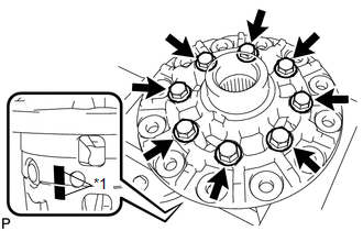
(a) Place matchmarks on the LH and RH cases.
Text in Illustration|
*1 |
Matchmark |
(b) Remove the 8 bolts.
NOTICE:
Loosen the bolts, diagonally opposite of each other, in pairs.
|
(c) Using a plastic-faced hammer, separate the LH and RH cases. |
|
.png)
|
(d) Remove the parts shown in the illustration from the differential case. Text in Illustration
|
|
.png)
 Removal
REMOVAL
PROCEDURE
1. REMOVE REAR AXLE SHAFT RH
(a) Remove the rear axle shaft RH (See page
).
2. REMOVE REAR AXLE SHAFT LH
HINT:
Use the same procedure described for the RH side.
3. REMOVE P ...
 Inspection
INSPECTION
PROCEDURE
1. INSPECT DIFFERENTIAL PINION AND SIDE GEAR
(a) Check that there is no damage to the differential pinion or differential
side gear.
If the differential pinion and/or differ ...
Other materials about Toyota 4Runner:
Room Temperature Sensor Circuit (B1411/11)
DESCRIPTION
The cooler thermistor (room temperature sensor) for the front seat is installed
in the instrument panel to detect the room temperature and control the heater and
air conditioner auto mode. The resistance of the room temperature sensor changes ...
Inspection
INSPECTION
PROCEDURE
1. CHECK BRAKE DISC INSIDE DIAMETER
(a) Using a brake drum gauge or equivalent, measure the inside diameter
of the disc.
Standard inside diameter:
210 mm (8.27 in.)
Maximum inside diameter:
211 mm (8.31 in.) ...

0.0276