Toyota 4Runner: Removal
REMOVAL
PROCEDURE
1. DISCONNECT CABLE FROM NEGATIVE BATTERY TERMINAL
CAUTION:
Wait at least 90 seconds after disconnecting the cable from the negative (-) battery terminal to disable the SRS system.
NOTICE:
When disconnecting the cable, some systems need to be initialized after the cable
is reconnected (See page .gif) ).
).
2. REMOVE NO. 1 INSTRUMENT CLUSTER FINISH PANEL GARNISH
3. REMOVE NO. 2 INSTRUMENT CLUSTER FINISH PANEL GARNISH
4. REMOVE HEATER CONTROL ASSEMBLY
5. REMOVE SHIFT LEVER KNOB SUB-ASSEMBLY
6. REMOVE SHIFT LEVER KNOB SUB-ASSEMBLY (for VF2A)
7. REMOVE UPPER CONSOLE PANEL SUB-ASSEMBLY
8. REMOVE NO. 2 CONSOLE BOX RETAINER
9. REMOVE LOWER CENTER INSTRUMENT CLUSTER FINISH PANEL SUB-ASSEMBLY
10. REMOVE REFRESHING SEAT SWITCH
|
(a) Detach the 4 claws to remove the refreshing seat switch. |
|
 Components
COMPONENTS
ILLUSTRATION
ILLUSTRATION
...
 Inspection
INSPECTION
PROCEDURE
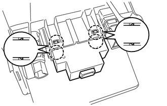
1. INSPECT REFRESHING SEAT SWITCH
Text in Illustration
*a
Component without harness connected
(Refreshing Seat Switch)
*b
Blowe ...
Other materials about Toyota 4Runner:
Terminals Of Ecu
TERMINALS OF ECU
1. TERMINALS OF ECU
Text in Illustration
*a
Component without harness connected
(Skid Control ECU)
-
-
Terminal No. (Symbol)
Terminal Description
...
Problem Symptoms Table
PROBLEM SYMPTOMS TABLE
HINT:
Use the table below to help determine the cause of problem symptoms.
If multiple suspected areas are listed, the potential causes of the symptoms
are listed in order of probability in the "Suspected Area" ...

0.0073