Toyota 4Runner: Removal
REMOVAL
PROCEDURE
1. DISCONNECT CABLE FROM NEGATIVE BATTERY TERMINAL
NOTICE:
When disconnecting the cable, some systems need to be initialized after the cable
is reconnected (See page .gif) ).
).
2. DISCONNECT CABLE FROM POSITIVE BATTERY TERMINAL
3. REMOVE BATTERY CLAMP
|
(a) Loosen the 2 nuts and remove the battery clamp. |
|
4. REMOVE BATTERY
5. REMOVE BATTERY TRAY
6. REMOVE V-BANK COVER
7. REMOVE FAN AND GENERATOR V BELT
8. REMOVE NO. 2 IDLER PULLEY SUB-ASSEMBLY
|
(a) for Integrated Type: Remove the bolt and No. 2 idler pulley. |
|
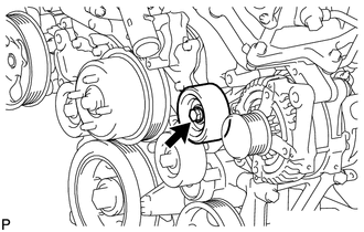
(b) for Separate Type:
Remove the bolt, No. 2 idler pulley cover plate, No. 2 idler pulley and idler pulley cover plate.
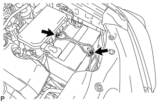
9. REMOVE WIRING HARNESS CLAMP BRACKET
|
(a) Detach the clamp. |
|
(b) Remove the bolt and wiring harness clamp bracket.
10. REMOVE NO. 2 EXHAUST MANIFOLD HEAT INSULATOR
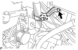
11. REMOVE GENERATOR ASSEMBLY
|
(a) Open the terminal cap. |
|
(b) Remove the nut and disconnect the wire harness from terminal B.
(c) Disconnect the generator connector from the generator assembly.
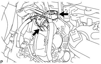
|
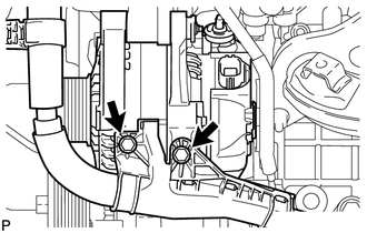
(d) Remove the 2 bolts and disconnect the wire harness. |
|
|
(e) Disconnect the wire harness clamp. |
|
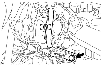
(f) Remove the bolt and disconnect the generator bracket.
|
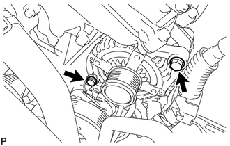
(g) Remove the 2 bolts and generator assembly. |
|
|
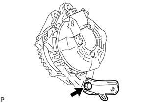
(h) Remove the bolt and generator bracket. |
|
 Components
COMPONENTS
ILLUSTRATION
ILLUSTRATION
...
 Disassembly
DISASSEMBLY
PROCEDURE
1. REMOVE GENERATOR PULLEY CAP
(a) Using a screwdriver, remove the generator pulley cap.
2. REMOVE GENERATOR WITH CLUTCH ...
Other materials about Toyota 4Runner:
Problem Symptoms Table
PROBLEM SYMPTOMS TABLE
HINT:
Use the table below to help determine the cause of problem symptoms.
If multiple suspected areas are listed, the potential causes of the symptoms
are listed in order of probability in the "Suspected Area" ...
Removal
REMOVAL
CAUTION / NOTICE / HINT
CAUTION:
Some of these service operations affect the SRS airbag system. Read the precautionary
notices concerning the SRS airbag system before servicing the steering column (See
page ).
PROCEDURE
1. PLACE FRONT WHEELS ...

0.026