Toyota 4Runner: Driver Side Seat Belt Warning Light does not Operate
DESCRIPTION
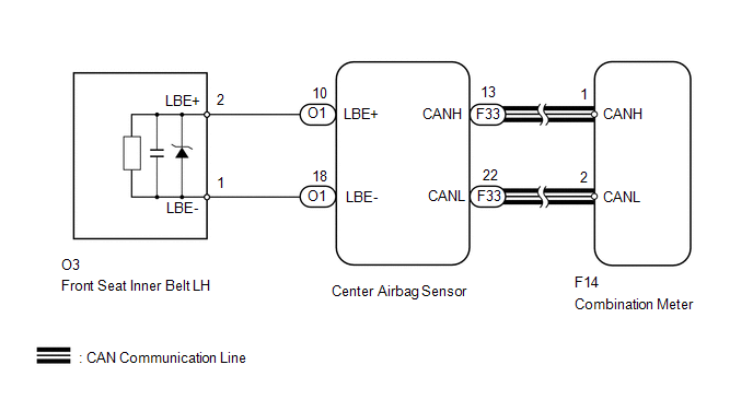
When the ignition switch is turned to ON, the center airbag sensor transmits front seat inner belt LH state signals to the combination meter through the CAN. If the driver side seat belt is not fastened, the combination meter blinks the driver side seat belt warning light. If the seat belt is fastened, the warning light goes off.
WIRING DIAGRAM
CAUTION / NOTICE / HINT
NOTICE:
The seat belt warning system uses the CAN communication system. First, confirm
that there is no malfunction in the CAN communication system. Refer to the How to
Proceed with Troubleshooting procedure (See page .gif)
).
PROCEDURE
|
1. |
CHECK FOR DTC (AIRBAG SYSTEM) |
(a) Clear the DTCs (See page ).
(b) Check for DTCs (See page ).
Result
|
Result |
Proceed to |
|---|---|
|
DTC is not output |
A |
|
Airbag system DTC is output |
B |
| B | .gif) |
GO TO AIRBAG SYSTEM |
|
.gif)
|
2. |
PERFORM ACTIVE TEST USING TECHSTREAM (DRIVER SIDE SEAT BELT WARNING LIGHT) |
(a) Operate the Techstream according to the display and select Active Test (See
page ).
Combination Meter
|
Item |
Test Part |
Control Range |
Diagnostic Note |
|---|---|---|---|
|
Driver Side Seat Belt |
Driver side seat belt warning light |
ON/OFF |
Confirm that the vehicle is stopped and the engine is idling. |
OK:
Driver side seat belt warning light condition can be switched by Active Test.
| NG | |
REPLACE COMBINATION METER ASSEMBLY |
|
|
3. |
REPLACE CENTER AIRBAG SENSOR ASSEMBLY |
(a) Temporarily replace the center airbag sensor with a new one (See page
).
|
|
4. |
CHECK DRIVER SIDE SEAT BELT WARNING LIGHT |
(a) Check the driver side seat belt warning light function (See page
).
OK:
Driver side seat belt warning light operates normally.
| OK | |
END (CENTER AIRBAG SENSOR IS DEFECTIVE) |
| NG | |
REPLACE COMBINATION METER ASSEMBLY |
 Data List / Active Test
DATA LIST / ACTIVE TEST
1. READ DATA LIST
HINT:
Using the Techstream to read the Data List allows values or states of switches,
sensors, actuators and other items to be read without removing any ...
 Front Passenger Side Seat Belt Warning Light Malfunction
DESCRIPTION
When the ignition switch is ON, the occupant detection ECU sends a signal to
the airbag sensor assembly to indicate the state of the front seat inner belt assembly
RH and also whether ...
Other materials about Toyota 4Runner:
Diagnosis System
DIAGNOSIS SYSTEM
1. SYMPTOM SIMULATION
HINT:
The most difficult case in troubleshooting is when no problem symptoms occur.
In such a case, a thorough problem analysis must be carried out. A simulation of
the same or similar conditions and environment in ...
Front Airbag Sensor LH Malfunction (B1615/14)
DESCRIPTION
The front airbag sensor LH consists of the diagnostic circuit and frontal deceleration
sensor, etc.
If the center airbag sensor receives signals from the frontal deceleration sensor,
it determines whether the SRS should be activated.
DTC B16 ...

0.0255