Toyota 4Runner: ECU Power Source Circuit
DESCRIPTION
This is the power source for the tire pressure warning ECU.
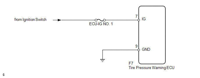
WIRING DIAGRAM
CAUTION / NOTICE / HINT
NOTICE:
- When replacing the tire pressure warning ECU, read the IDs stored in the old ECU using the Techstream and write them down before removal.
- It is necessary to perform registration of the transmitter IDs into
the tire pressure warning ECU after the ECU and/or the tire pressure warning
valve and transmitter has been replaced (See page
.gif) ).
). - Inspect the fuses for circuits related to this system before performing the following inspection procedure.
PROCEDURE
|
1. |
CHECK HARNESS AND CONNECTOR (ECU - BATTERY) |
|
(a) Disconnect the F7 ECU connector. |
|
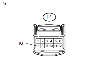
(b) Measure the voltage according to the value(s) in the table below.
Standard Voltage:
|
Tester Connection |
Switch Condition |
Specified Condition |
|---|---|---|
|
F7-7 (IG) - Body ground |
Ignition switch ON |
11 to 14 V |
|
Ignition switch off |
Below 1 V |
|
*a |
Front view of wire harness connector (to Tire Pressure Warning ECU) |
| NG | .gif) |
REPAIR OR REPLACE HARNESS OR CONNECTOR |
|
.gif)
|
2. |
CHECK HARNESS AND CONNECTOR (ECU - BODY GROUND) |
|
(a) Disconnect the F7 ECU connector. |
|
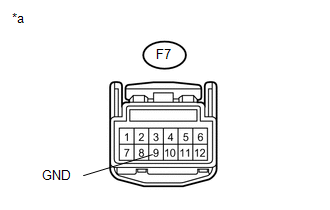
(b) Measure the resistance according to the value(s) in the table below.
Standard Resistance:
|
Tester Connection |
Condition |
Specified Condition |
|---|---|---|
|
F7-9 (GND) - Body ground |
Always |
Below 1 Ω |
|
*a |
Front view of wire harness connector (to Tire Pressure Warning ECU) |
| OK | |
REPLACE TIRE PRESSURE WARNING ECU |
| NG | |
REPAIR OR REPLACE HARNESS OR CONNECTOR |
 Tire Pressure Warning Light Circuit
DESCRIPTION
If the tire pressure warning ECU detects a disconnected connector or an open
circuit between the tire pressure warning ECU and combination meter, the tire pressure
warning light turns ...
 TC and CG Terminal Circuit
DESCRIPTION
DTC output mode is set by connecting terminals 13 (TC) and 4 (CG) of the DLC3.
The DTCs are output by the blinking of the tire pressure warning light.
WIRING DIAGRAM
HINT:
When eac ...
Other materials about Toyota 4Runner:
Removal
REMOVAL
CAUTION / NOTICE / HINT
HINT:
Use the same procedure for the RH and LH sides.
The procedure listed below is for the LH side.
PROCEDURE
1. REMOVE REAR NO. 1 FLOOR STEP COVER (w/ Rear No. 2 Seat)
2. REMOVE QUARTER SCUFF PLATE L ...
Disassembly
DISASSEMBLY
CAUTION / NOTICE / HINT
HINT:
Use the same procedure for the RH and LH sides.
The procedure listed below is for the LH side.
PROCEDURE
1. REMOVE FRONT FENDER OUTSIDE MOULDING PAD LH
(a) Remove the front fender outside moul ...

0.0266