Toyota 4Runner: Tire Pressure Warning Light Circuit
DESCRIPTION
If the tire pressure warning ECU detects a disconnected connector or an open circuit between the tire pressure warning ECU and combination meter, the tire pressure warning light turns off 10 seconds after the ignition switch is turned to ON, blinks for 1 minute, and then remains on.
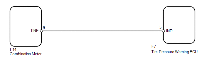
WIRING DIAGRAM
CAUTION / NOTICE / HINT
NOTICE:
- When replacing the tire pressure warning ECU, read the transmitter IDs stored in the old ECU using the Techstream and write them down before removal.
- It is necessary to perform registration of the transmitter IDs into
the tire pressure warning ECU after the ECU and/or the tire pressure warning
valve and transmitter has been replaced (See page
.gif) ).
).
PROCEDURE
|
1. |
CHECK HARNESS AND CONNECTOR (COMBINATION METER - TIRE PRESSURE WARNING ECU) |
(a) Disconnect the F14 meter connector.
(b) Disconnect the F7 ECU connector.
(c) Measure the resistance according to the value(s) in the table below.
Standard Resistance:
|
Tester Connection |
Condition |
Specified Condition |
|---|---|---|
|
F7-5 (IND) - F14-9 (TIRE) |
Always |
Below 1 Ω |
|
F7-5 (IND) - Body ground |
Always |
10 kΩ or higher |
| NG | .gif) |
REPAIR OR REPLACE HARNESS OR CONNECTOR |
|
.gif)
|
2. |
CHECK COMBINATION METER |
(a) Disconnect the F7 ECU connector.
(b) Turn the ignition switch to ON and check the condition of the tire pressure warning light illumination.
Result|
Result |
Proceed to |
|---|---|
|
Turns on after blinking for 1 minute |
A |
|
Does not turn on after blinking for 1 minute |
B |
| A | |
REPLACE TIRE PRESSURE WARNING ECU |
| B | |
REPLACE COMBINATION METER ASSEMBLY |
 Vehicle Speed Signal Error (Test Mode DTC) (C2191/91)
DESCRIPTION
The tire pressure warning ECU receives a vehicle speed signal from the combination
meter. This DTC is stored upon entering test mode and cleared when a vehicle speed
signal of 20 km/h ...
 ECU Power Source Circuit
DESCRIPTION
This is the power source for the tire pressure warning ECU.
WIRING DIAGRAM
CAUTION / NOTICE / HINT
NOTICE:
When replacing the tire pressure warning ECU, read the IDs stored ...
Other materials about Toyota 4Runner:
Disposal
DISPOSAL
PROCEDURE
1. DISPOSE OF CENTER CONTROL ABSORBER ASSEMBLY LH
(a) Using a drill, make a hole in the cylinder as shown in the illustration
to discharge the gas inside.
(b) Remove the flare nut. ...
Evaporator Temperature Sensor Circuit (B1413)
DESCRIPTION
The No. 1 cooler thermistor is installed on the evaporator in the air conditioning
unit to detect the temperature of the cooled air that has passed through the evaporator
and control the air conditioning. It sends appropriate signals to the No ...

0.0266