Toyota 4Runner: Front Clearance Sonar Sensor LH Circuit
DESCRIPTION
The ultrasonic sensor sends and receives ultrasonic waves. Based on the received wave, the sensor calculates the approximate distance between the vehicle and the obstacle, and sends the distance value as a signal to the clearance warning ECU assembly.
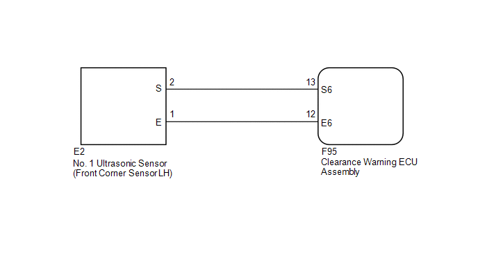
WIRING DIAGRAM
PROCEDURE
|
1. |
INSPECT NO. 1 ULTRASONIC SENSOR (FRONT CORNER SENSOR LH) |
(a) Remove the No. 1 ultrasonic sensor (front corner sensor LH) (See page
.gif) ).
).
(b) Inspect the No. 1 ultrasonic sensor (front corner sensor LH) (See page
).
| NG | .gif) |
REPLACE NO. 1 ULTRASONIC SENSOR (FRONT CORNER SENSOR LH) |
|
.gif)
|
2. |
CHECK HARNESS AND CONNECTOR (FRONT CORNER SENSOR LH - CLEARANCE WARNING ECU ASSEMBLY) |
(a) Disconnect the E2 No. 1 ultrasonic sensor (front corner sensor LH) connector.
(b) Disconnect the F95 clearance warning ECU assembly connector.
(c) Measure the resistance according to the value(s) in the table below.
Standard Resistance:
|
Tester Connection |
Condition |
Specified Condition |
|---|---|---|
|
E2-1 (E) - F95-12 (E6) |
Always |
Below 1 Ω |
|
E2-2 (S) - F95-13 (S6) |
Always |
Below 1 Ω |
|
E2-1 (E) - Body ground |
Always |
10 kΩ or higher |
|
E2-2 (S) - Body ground |
Always |
10 kΩ or higher |
| OK | |
PROCEED TO NEXT SUSPECTED AREA SHOWN IN PROBLEM SYMPTOMS TABLE |
| NG | |
REPAIR OR REPLACE HARNESS OR CONNECTOR |
 Back Sonar Sensor RH Circuit
DESCRIPTION
The ultrasonic sensor sends and receives ultrasonic waves. Based on the received
wave, the sensor calculates the approximate distance between the vehicle and the
obstacle, and sends t ...
 Front Clearance Sonar Sensor RH Circuit
DESCRIPTION
The ultrasonic sensor sends and receives ultrasonic waves. Based on the received
wave, the sensor calculates the approximate distance between the vehicle and the
obstacle, and sends t ...
Other materials about Toyota 4Runner:
TRAC OFF Indicator Light does not Come ON
DESCRIPTION
Refer to TRAC OFF Indicator Light Remains ON (See page
).
WIRING DIAGRAM
Refer to TRAC OFF Indicator Light Remains ON (See page
).
CAUTION / NOTICE / HINT
NOTICE:
When replacing the master cylinder solenoid, perform calibration (See page
...
Installation
INSTALLATION
CAUTION / NOTICE / HINT
HINT:
A bolt without a torque specification is shown in the standard bolt chart (See
page ).
PROCEDURE
1. INSTALL POWER STEERING ECU ASSEMBLY
(a) Attach the 2 claws to install the power steering ECU assembly.
2. I ...

0.0159