Toyota 4Runner: Front Differential Side Gear Shaft Oil Seal(for 4wd)
Components
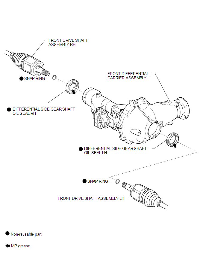
COMPONENTS
ILLUSTRATION
Replacement
REPLACEMENT
CAUTION / NOTICE / HINT
HINT:
- Use the same procedure for the RH and LH sides.
- The procedure listed below is for the LH side.
PROCEDURE
1. REMOVE FRONT DRIVE SHAFT ASSEMBLY LH
(a) Remove the front drive shaft assembly LH (See page
.gif) ).
).
2. REMOVE FRONT DRIVE SHAFT ASSEMBLY RH
HINT:
Use the same procedure described for the LH side.
3. REMOVE DIFFERENTIAL SIDE GEAR SHAFT OIL SEAL
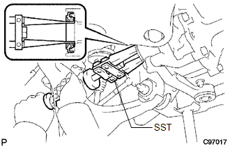
(a) Using SST, tap out the 2 oil seals.
SST: 09308-10010
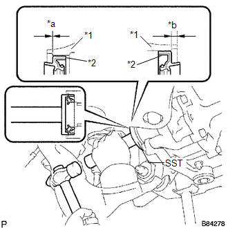
4. INSTALL DIFFERENTIAL SIDE GEAR SHAFT OIL SEAL
(a) Apply MP grease to 2 new oil seals.
|
(b) Using SST and a hammer, tap in the 2 oil seals. SST: 09550-00032 SST: 09950-70010 09951-07100 Standard Oil Seal Depth:
NOTICE: Make sure the LH and RH oil seals are installed in the proper locations. |
|
5. INSTALL FRONT DRIVE SHAFT ASSEMBLY LH
(a) Install the front drive shaft assembly LH (See page
).
6. INSTALL FRONT DRIVE SHAFT ASSEMBLY RH
HINT:
Use the same procedure described for the LH side.
 Front Differential Carrier Oil Seal(for 4wd)
Components
COMPONENTS
ILLUSTRATION
Replacement
REPLACEMENT
PROCEDURE
1. REMOVE FRONT DIFFERENTIAL CARRIER ASSEMBLY
(a) Remove the front differential carrier assembly (See page
).
2. RE ...
 Rear Axle Hub Bolt
Components
COMPONENTS
ILLUSTRATION
Replacement
REPLACEMENT
CAUTION / NOTICE / HINT
HINT:
Use the same procedure for the RH and LH sides.
The procedure listed below is for the ...
Other materials about Toyota 4Runner:
Problem Symptoms Table
PROBLEM SYMPTOMS TABLE
HINT:
Use the table below to help determine the cause of problem symptoms.
If multiple suspected areas are listed, the potential causes of the symptoms
are listed in order of probability in the "Suspected Area" ...
Reassembly
REASSEMBLY
PROCEDURE
1. INSTALL FOG LIGHT COVER LH
(a) Attach the 5 claws to install the fog light cover LH.
(b) Install the outside moulding retainer.
2. INSTALL FOG LIGHT COVER RH
HINT:
Use the same procedure as for the LH side.
3. INSTALL FOG LIGHT ...

0.0066