
Toyota 4Runner: Rear Axle Hub Bolt
Components
COMPONENTS
ILLUSTRATION
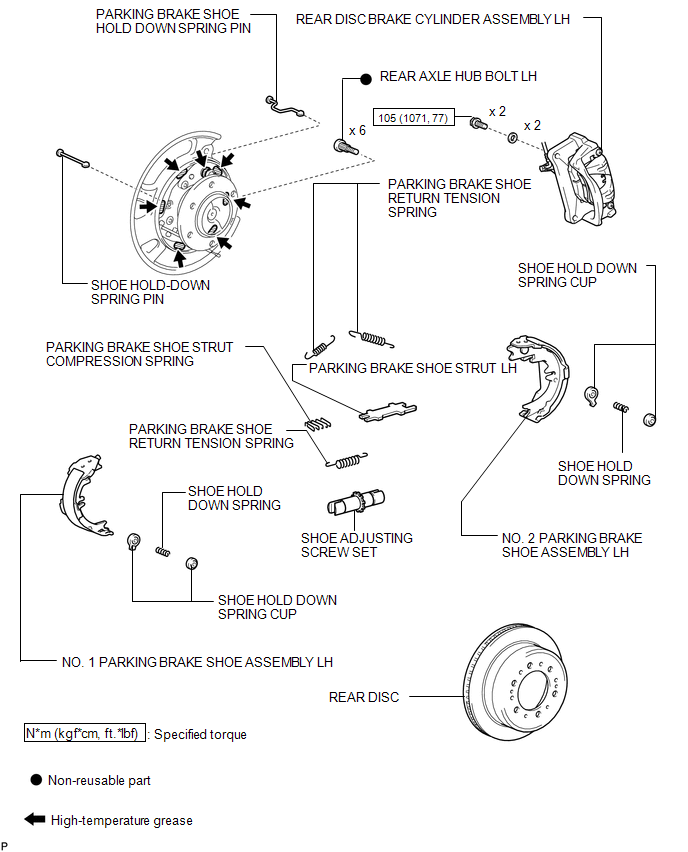
Replacement
REPLACEMENT
CAUTION / NOTICE / HINT
HINT:
- Use the same procedure for the RH and LH sides.
- The procedure listed below is for the LH side.
PROCEDURE
1. REMOVE REAR WHEEL
2. REMOVE PARKING BRAKE ASSEMBLY
(a) Remove the parking brake assembly (See page
.gif) ).
).
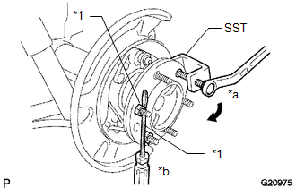
3. REMOVE REAR AXLE HUB BOLT LH
|
(a) Using SST and a screwdriver or equivalent to hold the axle hub, remove the hub bolt. SST: 09650-17011 Text in Illustration
NOTICE:
|
|
4. INSTALL REAR AXLE HUB BOLT LH
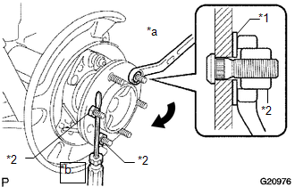
(a) Insert a new hub bolt.
(b) Temporarily install a washer and hub nut to the hub bolt as shown in the illustration.
Text in Illustration|
*1 |
Washer |
|
*2 |
Nut |
|
*a |
Turn |
|
*b |
Hold |
NOTICE:
Install a hub nut to prevent damage to the hub bolt.
(c) Using a screwdriver or equivalent to hold the hub, turn the hub nut until the bottom surface of the hub bolt head touches the axle hub.
(d) Remove the hub nut and washer.
NOTICE:
Do not damage the threads of the hub bolt.
5. INSTALL PARKING BRAKE ASSEMBLY
(a) Install the parking brake assembly (See page
).
6. INSTALL REAR WHEEL
Torque:
for aluminum wheel :
103 N·m {1050 kgf·cm, 76 ft·lbf}
for steel wheel :
112 N·m {1142 kgf·cm, 83 ft·lbf}
 Front Differential Side Gear Shaft Oil Seal(for 4wd)
Components
COMPONENTS
ILLUSTRATION
Replacement
REPLACEMENT
CAUTION / NOTICE / HINT
HINT:
Use the same procedure for the RH and LH sides.
The procedure listed below is for the ...
 Rear Axle Shaft
...
Other materials about Toyota 4Runner:
Removal
REMOVAL
PROCEDURE
1. REMOVE UPPER RADIATOR SUPPORT SEAL
2. REMOVE FRONT BUMPER COVER
(a) Put protective tape around the front bumper cover.
(b) Remove the 3 bolts, 10 screws and 6 clips.
(c) Detach the 14 claws to remove the front bumper cover with ra ...
Back-up Power Source Circuit
DESCRIPTION
The back-up power source circuit for the air conditioning amplifier assembly
is shown below. Power is supplied even after the ignition switch is turned off and
is used for diagnostic trouble code memory, etc.
WIRING DIAGRAM
CAUTION / NOTIC ...

0.0234