Toyota 4Runner: Roof Rack
Components
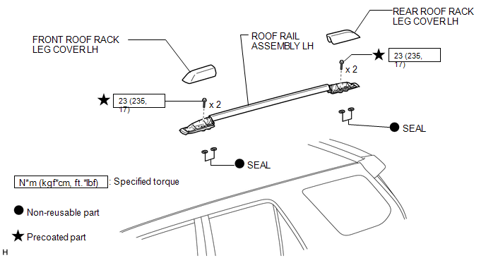
COMPONENTS
ILLUSTRATION
ILLUSTRATION
Removal
REMOVAL
CAUTION / NOTICE / HINT
HINT:
- Use the same procedure for the RH and LH sides.
- The procedure listed below is for the LH side.
PROCEDURE
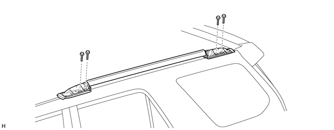
1. REMOVE FRONT ROOF RACK LEG COVER LH
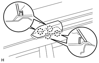
(a) Detach the 4 claws and remove the front roof rack leg cover.
2. REMOVE REAR ROOF RACK LEG COVER LH
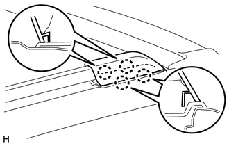
(a) Detach the 4 claws and remove the rear roof rack leg cover.
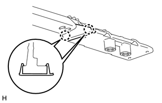
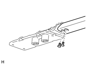
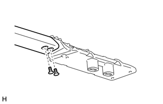
3. REMOVE ROOF RAIL ASSEMBLY LH
(a) Remove the 4 bolts and roof rail.
Disassembly
DISASSEMBLY
CAUTION / NOTICE / HINT
HINT:
- Use the same procedure for the RH and LH sides.
- The procedure listed below is for the LH side.
PROCEDURE
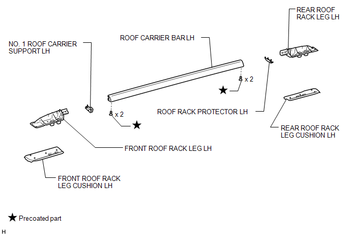
1. REMOVE FRONT ROOF RACK LEG CUSHION LH
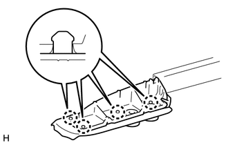
(a) Detach the 4 claws and remove the front roof rack leg cushion.
2. REMOVE REAR ROOF RACK LEG CUSHION LH
(a) Detach the 4 claws and remove the rear roof rack leg cushion.
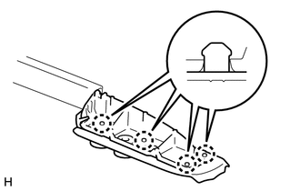
3. REMOVE NO. 1 ROOF CARRIER SUPPORT LH
(a) Detach the 2 claws and remove the No. 1 roof carrier support.
4. REMOVE ROOF RACK PROTECTOR LH
(a) Detach the 2 claws and remove the roof rack protector.
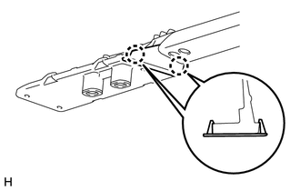
5. REMOVE FRONT ROOF RACK LEG LH
(a) Using a T30 "TORX" socket wrench, remove the 2 screws and front roof rack leg.
6. REMOVE REAR ROOF RACK LEG LH
(a) Using a T30 "TORX" socket wrench, remove the 2 screws and rear roof rack leg.
Reassembly
REASSEMBLY
CAUTION / NOTICE / HINT
HINT:
- Use the same procedure for the RH and LH sides.
- The procedure listed below is for the LH side.
PROCEDURE
1. INSTALL FRONT ROOF RACK LEG LH
(a) Clean the threads of the bolt with non-residue solvent (when reusing the bolt).
(b) Apply adhesive to the threads of the bolt (when reusing the bolt).
Adhesive:
Toyota Genuine Adhesive 1324, Three Bond 1324 or equivalent.
(c) Using a T30 "TORX" socket wrench, install the front roof rack leg with the 2 bolts.
2. INSTALL REAR ROOF RACK LEG LH
(a) Clean the threads of the bolt with non-residue solvent (when reusing the bolt).
(b) Apply adhesive to the threads of the bolt (when reusing the bolt).
Adhesive:
Toyota Genuine Adhesive 1324, Three Bond 1324 or equivalent.
(c) Using a T30 "TORX" socket wrench, install the rear roof rack leg with the 2 bolts.
3. INSTALL NO. 1 ROOF CARRIER SUPPORT LH
(a) Attach the 2 claws to install the No. 1 roof carrier support.
4. INSTALL ROOF RACK PROTECTOR LH
(a) Attach the 2 claws to install the roof rack protector.
5. INSTALL FRONT ROOF RACK LEG CUSHION LH
(a) Attach the 4 claws to install the front roof rack leg cushion.
6. INSTALL REAR ROOF RACK LEG CUSHION LH
(a) Attach the 4 claws to install the rear roof rack leg cushion.
Installation
INSTALLATION
CAUTION / NOTICE / HINT
HINT:
- Use the same procedure for the RH and LH sides.
- The procedure listed below is for the LH side.
PROCEDURE
1. INSTALL ROOF RAIL ASSEMBLY LH
(a) Clean the threads of the bolt with non-residue solvent (when reusing the bolt).
(b) Apply adhesive to the threads of the bolt (when reusing the bolt).
Adhesive:
Toyota Genuine Adhesive 1324, Three Bond 1324 or equivalent.
(c) Install the roof rail with the 4 bolts.
Torque:
23 N·m {235 kgf·cm, 17 ft·lbf}
2. INSTALL FRONT ROOF RACK LEG COVER LH
(a) Attach the 4 claws to install the front roof rack leg cover.
3. INSTALL REAR ROOF RACK LEG COVER LH
(a) Attach the 4 claws to install the rear roof rack leg cover.
 Installation
INSTALLATION
CAUTION / NOTICE / HINT
HINT:
Use the same procedure for the RH and LH sides.
The procedure listed below is for the LH side.
When installing the clip, heat the vehicle ...
 Side Moulding
...
Other materials about Toyota 4Runner:
Removal
REMOVAL
PROCEDURE
1. DISCONNECT CABLE FROM NEGATIVE BATTERY TERMINAL
CAUTION:
Wait at least 90 seconds after disconnecting the cable from the negative (-)
battery terminal to disable the SRS system.
NOTICE:
When disconnecting the cable, some systems ne ...
Inspection
INSPECTION
PROCEDURE
1. INSPECT SPIRAL CABLE SUB-ASSEMBLY
(a) If there are any defects as mentioned below, replace the spiral cable with
a new one:
Scratches, cracks, dents or chips in the connector or spiral cable.
(b) Check the spiral cable.
Text in ...

0.0069