Toyota 4Runner: Front Vertical Sensor Malfunction (B2652)
DESCRIPTION
When the front power seat switch LH does not receive a sensor signal despite upward or downward movement of the front of the seat cushion by power seat motor operation, this DTC is stored.
|
DTC Code |
DTC Detection Condition |
Trouble Area |
|---|---|---|
|
B2652 |
The upward and downward lock detection position of the sensor is the same. |
|
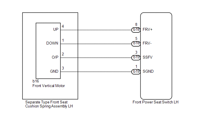
WIRING DIAGRAM
PROCEDURE
|
1. |
PERFORM ACTIVE TEST USING TECHSTREAM (POWER SEAT MOTOR FUNCTION) |
(a) Select the Active Test, use the Techstream to generate a control command,
and then check the power seat motor function (See page
.gif) ).
).
Driver Seat
|
Tester Display |
Test Part |
Control Range |
Diagnostic Note |
|---|---|---|---|
|
Front Vertical Operation |
Seat front vertical operation |
Up / OFF / Down |
- |
OK:
Motor operates normally.
| NG | .gif) |
GO TO STEP 5 |
|
.gif)
|
2. |
CHECK FRONT POWER SEAT SWITCH LH (FRONT VERTICAL MOTOR CIRCUIT) |
|
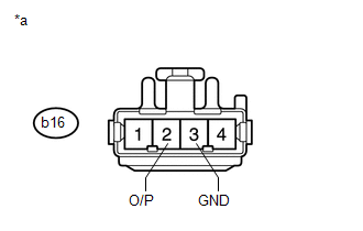
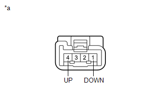
(a) Disconnect the b16 front vertical motor connector. |
|
(b) Measure the voltage according to the value(s) in the table below.
Standard Voltage:
|
Tester Connection |
Switch Condition |
Specified Condition |
|---|---|---|
|
b16-2 (O/P) - b16-3 (GND) |
Front vertical switch on |
4.8 to 5.1 V |
|
*a |
Front view of wire harness connector (to Separate Type Front Seat Cushion Spring Assembly LH [Front Vertical Motor]) |
| NG | |
GO TO STEP 4 |
|
|
3. |
CHECK SEPARATE TYPE FRONT SEAT CUSHION SPRING ASSEMBLY LH (FRONT VERTICAL MOTOR) |
|
(a) Connect the b16 front vertical motor connector. |
|
(b) Measure the voltage according to the value(s) in the table below.
Standard Voltage:
|
Tester Connection |
Switch Condition |
Specified Condition |
|---|---|---|
|
b16-2 (O/P) - Body ground |
Front vertical switch on |
4.5 to 4.8 V |
|
*a |
Component with harness connected (Separate Type Front Seat Cushion Spring Assembly LH [Front Vertical Motor]) |
| OK | |
REPLACE FRONT POWER SEAT SWITCH LH |
| NG | |
REPLACE SEPARATE TYPE FRONT SEAT CUSHION SPRING ASSEMBLY LH (FRONT VERTICAL MOTOR) |
|
4. |
CHECK HARNESS AND CONNECTOR (FRONT POWER SEAT SWITCH LH - FRONT VERTICAL MOTOR) |
(a) Disconnect the b19 front power seat switch LH connector.
(b) Disconnect the b16 front vertical motor connector.
(c) Measure the resistance according to the value(s) in the table below.
Standard Resistance:
|
Tester Connection |
Condition |
Specified Condition |
|---|---|---|
|
b19-3 (SSFV) - b16-2 (O/P) |
Always |
Below 1 Ω |
|
b19-1 (SGND) - b16-3 (GND) |
Always |
Below 1 Ω |
|
b19-3 (SSFV) - Body ground |
Always |
10 kΩ or higher |
|
b19-1 (SGND) - Body ground |
Always |
10 kΩ or higher |
| OK | |
REPLACE FRONT POWER SEAT SWITCH LH |
| NG | |
REPAIR OR REPLACE HARNESS OR CONNECTOR |
|
5. |
INSPECT SEPARATE TYPE FRONT SEAT CUSHION SPRING ASSEMBLY LH (FRONT VERTICAL MOTOR) |
|
(a) Remove the separate type front seat cushion spring assembly LH (front
vertical motor) (See page |
|
(b) Disconnect the b16 front vertical motor.
(c) Check if the seat cushion spring moves smoothly when the battery is connected to the front vertical motor connector terminals.
OK:
|
Measurement Condition |
Operational Direction |
|---|---|
|
Battery positive (+) → 4 (UP) Battery negative (-) → 1 (DOWN) |
Seat cushion spring moves upward |
|
Battery positive (+) → 1 (DOWN) Battery negative (-) → 4 (UP) |
Seat cushion spring moves downward |
|
*a |
Component without harness connected (Separate Type Front Seat Cushion Spring Assembly LH [Front Vertical Motor]) |
| NG | |
REPLACE SEPARATE TYPE FRONT SEAT CUSHION SPRING ASSEMBLY LH (FRONT VERTICAL MOTOR) |
|
|
6. |
CHECK HARNESS AND CONNECTOR (FRONT POWER SEAT SWITCH LH - FRONT VERTICAL MOTOR) |
(a) Disconnect the b18 front power seat switch LH connector.
(b) Disconnect the b16 front vertical motor connector.
(c) Measure the resistance according to the value(s) in the table below.
Standard Resistance:
|
Tester Connection |
Condition |
Specified Condition |
|---|---|---|
|
b18-8 (FRV+) - b16-4 (UP) |
Always |
Below 1 Ω |
|
b18-5 (FRV-) - b16-1 (DOWN) |
Always |
Below 1 Ω |
|
b18-8 (FRV+) - Body ground |
Always |
10 kΩ or higher |
|
b18-5 (FRV-) - Body ground |
Always |
10 kΩ or higher |
| OK | |
REPLACE FRONT POWER SEAT SWITCH LH |
| NG | |
REPAIR OR REPLACE HARNESS OR CONNECTOR |
 Reclining Sensor Malfunction (B2651)
DESCRIPTION
When the front power seat switch LH does not receive a sensor signal despite
forward or backward movement of the seatback by power seat motor operation, this
DTC is stored.
...
 Slide Sensor Malfunction (B2650)
DESCRIPTION
When the front power seat switch LH does not receive a sensor signal despite
forward or backward movement of the seat by power seat motor operation, this DTC
is stored.
DT ...
Other materials about Toyota 4Runner:
Short in Front Passenger Side Squib 2nd Step Circuit (B1815/54-B1818/54)
DESCRIPTION
The front passenger side squib 2nd step circuit consists of the center airbag
sensor and instrument panel passenger airbag.
The circuit instructs the SRS to deploy when deployment conditions are met.
These DTCs are stored when a malfunction is ...
Reassembly
REASSEMBLY
PROCEDURE
1. INSTALL TRANSFER POSITION SWITCH (for VF2BM)
2. INSTALL TRANSFER POSITION SWITCH (for VF4BM)
3. INSTALL NO. 2 BOX BOTTOM MAT (for 2WD)
(a) Attach the 4 claws to install the No. 2 box bottom mat.
4. INSTALL FRONT UPPER CONSOL ...

0.0256