Toyota 4Runner: Slide Sensor Malfunction (B2650)
DESCRIPTION
When the front power seat switch LH does not receive a sensor signal despite forward or backward movement of the seat by power seat motor operation, this DTC is stored.
|
DTC Code |
DTC Detection Condition |
Trouble Area |
|---|---|---|
|
B2650 |
The forward and backward lock detection position of the sensor is the same. |
|
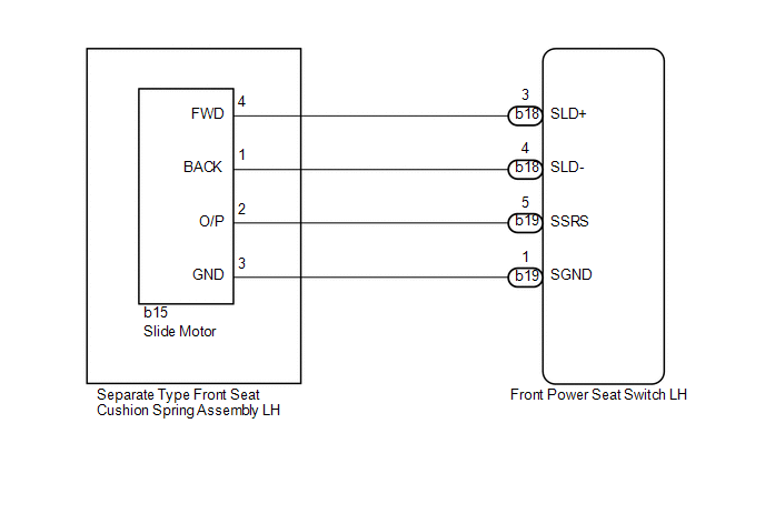
WIRING DIAGRAM
PROCEDURE
|
1. |
PERFORM ACTIVE TEST USING TECHSTREAM (POWER SEAT MOTOR FUNCTION) |
(a) Select the Active Test, use the Techstream to generate a control command,
and then check the power seat motor function (See page
.gif) ).
).
Driver Seat
|
Tester Display |
Test Part |
Control Range |
Diagnostic Note |
|---|---|---|---|
|
Seat Slide Operation |
Seat sliding operation |
Front / OFF / Rear |
- |
OK:
Motor operates normally.
| NG | .gif) |
GO TO STEP 5 |
|
.gif)
|
2. |
CHECK FRONT POWER SEAT SWITCH LH (SLIDE MOTOR CIRCUIT) |
|
(a) Disconnect the b15 slide motor connector. |
|
(b) Measure the voltage according to the value(s) in the table below.
Standard Voltage:
|
Tester Connection |
Switch Condition |
Specified Condition |
|---|---|---|
|
b15-2 (O/P) - b15-3 (GND) |
Sliding switch on |
4.8 to 5.1 V |
|
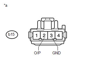
*a |
Front view of wire harness connector (to Separate Type Front Seat Cushion Spring Assembly LH [Slide Motor]) |
| NG | |
GO TO STEP 4 |
|
|
3. |
CHECK SEPARATE TYPE FRONT SEAT CUSHION SPRING ASSEMBLY LH (SLIDE MOTOR) |
|
(a) Connect the b15 slide motor connector. |
|
(b) Measure the voltage according to the value(s) in the table below.
Standard Voltage:
|
Tester Connection |
Switch Condition |
Specified Condition |
|---|---|---|
|
b15-2 (O/P) - Body ground |
Sliding switch on |
4.5 to 4.8 V |
|
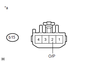
*a |
Component with harness connected (Separate Type Front Seat Cushion Spring Assembly LH [Slide Motor]) |
| OK | |
REPLACE FRONT POWER SEAT SWITCH LH |
| NG | |
REPLACE SEPARATE TYPE FRONT SEAT CUSHION SPRING ASSEMBLY LH (SLIDE MOTOR) |
|
4. |
CHECK HARNESS AND CONNECTOR (FRONT POWER SEAT SWITCH - SLIDE MOTOR) |
(a) Disconnect the b19 front power seat switch LH connector.
(b) Disconnect the b15 slide motor connector.
(c) Measure the resistance according to the value(s) in the table below.
Standard Resistance:
|
Tester Connection |
Condition |
Specified Condition |
|---|---|---|
|
b19-5 (SSRS) - b15-2 (O/P) |
Always |
Below 1 Ω |
|
b19-1 (SGND) - b15-3 (GND) |
Always |
Below 1 Ω |
|
b19-5 (SSRS) - Body ground |
Always |
10 kΩ or higher |
|
b19-1 (SGND) - Body ground |
Always |
10 kΩ or higher |
| OK | |
REPLACE FRONT POWER SEAT SWITCH LH |
| NG | |
REPAIR OR REPLACE HARNESS OR CONNECTOR |
|
5. |
INSPECT SEPARATE TYPE FRONT SEAT CUSHION SPRING ASSEMBLY LH (SLIDE MOTOR) |
|
(a) Remove the separate type front seat cushion spring assembly LH (slide
motor) (See page |
|
(b) Disconnect the b15 slide motor connector.
(c) Check if the seat cushion spring moves smoothly when the battery is connected to the slide motor connector terminals.
OK:
|
Measurement Condition |
Specified Condition |
|---|---|
|
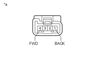
Battery positive (+) → 4 (FWD) Battery negative (-) → 1 (BACK) |
Front seat cushion spring assembly LH moves forward |
|
Battery positive (+) → 1 (BACK) Battery negative (-) → 4 (FWD) |
Front seat cushion spring assembly LH moves backward |
|
*a |
Component without harness connected (Separate Type Front Seat Cushion Spring Assembly LH [Slide Motor]) |
| NG | |
REPLACE SEPARATE TYPE FRONT SEAT CUSHION SPRING ASSEMBLY LH (SLIDE MOTOR) |
|
|
6. |
CHECK HARNESS AND CONNECTOR (FRONT POWER SEAT SWITCH LH - SLIDE MOTOR) |
(a) Disconnect the b18 front power seat switch LH connector.
(b) Disconnect the b15 slide motor connector.
(c) Measure the resistance according to the value(s) in the table below.
Standard Resistance:
|
Tester Connection |
Condition |
Specified Condition |
|---|---|---|
|
b18-3 (SLD+) - b15-4 (FWD) |
Always |
Below 1 Ω |
|
b18-4 (SLD-) - b15-1 (BACK) |
Always |
Below 1 Ω |
|
b18-3 (SLD+) - Body ground |
Always |
10 kΩ or higher |
|
b18-4 (SLD-) - Body ground |
Always |
10 kΩ or higher |
| OK | |
REPLACE FRONT POWER SEAT SWITCH LH |
| NG | |
REPAIR OR REPLACE HARNESS OR CONNECTOR |
 Front Vertical Sensor Malfunction (B2652)
DESCRIPTION
When the front power seat switch LH does not receive a sensor signal despite
upward or downward movement of the front of the seat cushion by power seat motor
operation, this DTC is st ...
 Front Power Seat does not Operate with Front Power Seat Switch
DESCRIPTION
When a signal is input into the front power seat switch LH (position control
ECU), the ECU manages the signals received from the front power seat switch LH and
operates each motor. Wh ...
Other materials about Toyota 4Runner:
Terminals Of Ecu
TERMINALS OF ECU
1. CHECK MAIN BODY ECU (MULTIPLEX NETWORK BODY ECU) AND DRIVER SIDE JUNCTION
BLOCK ASSEMBLY
(a) Remove the main body ECU (multiplex network body ECU) from the driver side
junction block assembly (See page ).
(b) Measure the resistanc ...
Installation
INSTALLATION
CAUTION / NOTICE / HINT
CAUTION:
Wear protective gloves. Sharp areas on the parts may injure your hands.
HINT:
Use the same procedure for the power seat RH and power seat LH sides.
The procedure listed below is for the power se ...

0.0083