Toyota 4Runner: Reclining Sensor Malfunction (B2651)
DESCRIPTION
When the front power seat switch LH does not receive a sensor signal despite forward or backward movement of the seatback by power seat motor operation, this DTC is stored.
|
DTC Code |
DTC Detection Condition |
Trouble Area |
|---|---|---|
|
B2651 |
The forward and backward lock detection position of the sensor is the same. |
|
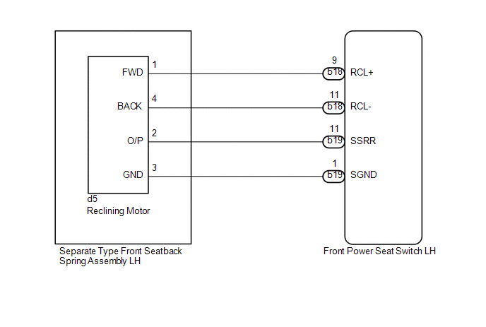
WIRING DIAGRAM
PROCEDURE
|
1. |
PERFORM ACTIVE TEST USING TECHSTREAM (POWER SEAT MOTOR FUNCTION) |
(a) Select the Active Test, use the Techstream to generate a control command,
and then check the power seat motor function (See page
.gif) ).
).
Driver Seat
|
Tester Display |
Test Part |
Control Ranger |
Diagnostic Note |
|---|---|---|---|
|
Seat Reclining |
Seat reclining operation |
Front / OFF / Rear |
- |
OK:
Motor operates normally.
| NG | .gif) |
GO TO STEP 5 |
|
.gif)
|
2. |
CHECK FRONT POWER SEAT SWITCH LH (RECLINING MOTOR CIRCUIT) |
|
(a) Disconnect the d5 reclining motor connector. |
|
(b) Measure the voltage according to the value(s) in the table below.
Standard Voltage:
|
Tester Connection |
Switch Condition |
Specified Condition |
|---|---|---|
|
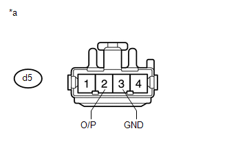
d5-2 (O/P) - d5-3 (GND) |
Reclining switch on |
4.8 to 5.1 V |
|
*a |
Front view of wire harness connector (to Separate Type Front Seatback Spring Assembly LH [Reclining Motor]) |
| NG | |
GO TO STEP 4 |
|
|
3. |
CHECK SEPARATE TYPE FRONT SEATBACK SPRING ASSEMBLY LH (RECLINING MOTOR) |
|
(a) Connect the d5 reclining motor connector. |
|
(b) Measure the voltage according to the value(s) in the table below.
Standard Voltage:
|
Tester Connection |
Switch Condition |
Specified Condition |
|---|---|---|
|
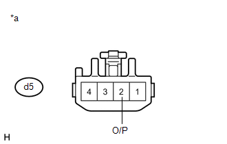
d5-2 (O/P) - Body ground |
Reclining switch on |
4.5 to 4.8 V |
|
*a |
Component with harness connected (Separate Type Front Seatback Spring Assembly LH [Reclining Motor]) |
| OK | |
REPLACE FRONT POWER SEAT SWITCH LH |
| NG | |
REPLACE SEPARATE TYPE FRONT SEATBACK SPRING ASSEMBLY LH (RECLINING MOTOR) |
|
4. |
CHECK HARNESS AND CONNECTOR (FRONT POWER SEAT SWITCH - RECLINING MOTOR) |
(a) Disconnect the b19 front power seat switch LH connector.
(b) Disconnect the d5 reclining motor connector.
(c) Measure the resistance according to the value(s) in the table below.
Standard Resistance:
|
Tester Connection |
Condition |
Specified Condition |
|---|---|---|
|
b19-11 (SSRR) - d5-2 (O/P) |
Always |
Below 1 Ω |
|
b19-1 (SGND) - d5-3 (GND) |
Always |
Below 1 Ω |
|
b19-11 (SSRR) - Body ground |
Always |
10 kΩ or higher |
|
b19-1 (SGND) - Body ground |
Always |
10 kΩ or higher |
| OK | |
REPLACE FRONT POWER SEAT SWITCH LH |
| NG | |
REPAIR OR REPLACE HARNESS OR CONNECTOR |
|
5. |
INSPECT SEPARATE TYPE FRONT SEATBACK SPRING ASSEMBLY LH (RECLINING MOTOR) |
|
(a) Remove the front seatback board sub-assembly (See page
|
|
(b) Disconnect the b5 reclining motor connector.
(c) Check if the seatback moves smoothly when the battery is connected to the reclining motor connector terminals.
OK:
|
Measurement Condition |
Operational Direction |
|---|---|
|
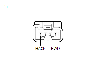
Battery positive (+) → 1 (FWD) Battery negative (-) → 4 (BACK) |
Seatback moves forward |
|
Battery positive (+) → 4 (BACK) Battery negative (-) → 1 (FWD) |
Seatback moves backward |
|
*a |
Component without harness connected (Separate Type Front Seatback Spring Assembly LH [Reclining Motor]) |
| NG | |
REPLACE SEPARATE TYPE FRONT SEATBACK SPRING ASSEMBLY LH (RECLINING MOTOR) |
|
|
6. |
CHECK HARNESS AND CONNECTOR (FRONT POWER SEAT SWITCH LH - RECLINING MOTOR) |
(a) Disconnect the b18 front power seat switch LH connector.
(b) Disconnect the d5 reclining motor connector.
(c) Measure the resistance according to the value(s) in the table below.
Standard Resistance:
|
Tester Connection |
Condition |
Specified Condition |
|---|---|---|
|
b18-9 (RCL+) - d5-1 (FWD) |
Always |
Below 1 Ω |
|
b18-11 (RCL-) - d5-4 (BACK) |
Always |
Below 1 Ω |
|
b18-9 (RCL+) - Body ground |
Always |
10 kΩ or higher |
|
b18-11 (RCL-) - Body ground |
Always |
10 kΩ or higher |
| OK | |
REPLACE FRONT POWER SEAT SWITCH LH |
| NG | |
REPAIR OR REPLACE HARNESS OR CONNECTOR |
 Short in Sensor with Motor Power Supply Circuit (B2658)
DESCRIPTION
This DTC is stored when a power seat motor operates (a position control sensor
is being supplied with power) and the power supply voltage does not rise to the
specified value.
...
 Front Vertical Sensor Malfunction (B2652)
DESCRIPTION
When the front power seat switch LH does not receive a sensor signal despite
upward or downward movement of the front of the seat cushion by power seat motor
operation, this DTC is st ...
Other materials about Toyota 4Runner:
Data List / Active Test
DATA LIST / ACTIVE TEST
1. READ DATA LIST
HINT:
Using the Techstream to read the Data List allows the values or states of switches,
sensors, actuators and other items to be read without removing any parts. This non-intrusive
inspection can be very usefu ...
Detachable pole antenna
The antenna can be removed.
Removing the antenna
Place the included wrench around the antenna.
When not in use, the wrench is stored in glove box.
Loosen the antenna with the wrench and remove it.
Installing the antenna
Tighten the antenna by one h ...

0.0115