Toyota 4Runner: High Mounted Stop Light Assembly
Components
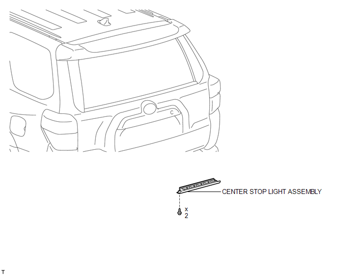
COMPONENTS
ILLUSTRATION
Removal
REMOVAL
PROCEDURE
1. REMOVE CENTER STOP LIGHT ASSEMBLY
|
(a) Remove the 2 screws and stop light. |
|
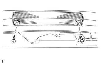
(b) Disconnect the connector.
Inspection
INSPECTION
PROCEDURE
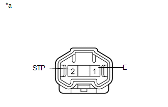
1. INSPECT CENTER STOP LIGHT ASSEMBLY
|
(a) Apply battery voltage to the connector and check the LED illumination condition. OK:
If the result is not as specified, replace the center stop light assembly. Text in Illustration
|
|
Installation
INSTALLATION
PROCEDURE
1. INSTALL CENTER STOP LIGHT ASSEMBLY
(a) Connect the connector.
(b) Install the stop light with the 2 screws.
 Installation
INSTALLATION
PROCEDURE
1. INSTALL HEADLIGHT DIMMER SWITCH ASSEMBLY
(a) Install the headlight dimmer switch to the steering column, making
sure that the stopper protrusions and cutout ...
 License Plate Light Assembly
Components
COMPONENTS
ILLUSTRATION
Removal
REMOVAL
PROCEDURE
1. REMOVE OUTSIDE BACK DOOR GARNISH
(a) Remove the outside back door garnish (See page
).
2. REMOVE LICENSE PLATE LIGHT ASS ...
Other materials about Toyota 4Runner:
Operating Light Control Rheostat does not Change Light Brightness
DESCRIPTION
When the light control rheostat dial is turned upward, the combination meter
and vehicle interior illumination will become brighter. When the light control rheostat
dial is turned downward, the combination meter and vehicle illumination will d ...
Remote Up / Down Function does not Operate
DESCRIPTION
When the ignition switch is ON and the window lock switch is off, the multiplex
network master switch sends remote up/down signals to each power window regulator
motor via the LIN communication line.
PROCEDURE
1.
CHECK ...

0.0128