Toyota 4Runner: Horn System
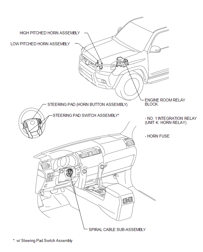
Parts Location
PARTS LOCATION
ILLUSTRATION
Problem Symptoms Table
PROBLEM SYMPTOMS TABLE
HINT:
Use the table below to help determine the cause of problem symptoms. If multiple suspected areas are listed, the potential causes of the symptoms are listed in order of probability in the "Suspected Area" column of the table. Check each symptom by checking the suspected areas in the order they are listed. Replace parts as necessary.
Horn System|
Symptom |
Suspected Area |
See page |
|---|---|---|
|
Horn does not sound |
HORN fuse |
|
|
Low pitched horn assembly |
|
|
|
High pitched horn assembly |
|
|
|
Engine room relay block (No. 1 integration relay) |
|
|
|
Steering pad (Horn button assembly) |
|
|
|
Steering pad switch assembly* |
- |
|
|
Spiral cable sub-assembly |
|
|
|
Harness or connector |
- |
.gif)
- *: w/ Steering Pad Switch Assembly
System Diagram
SYSTEM DIAGRAM
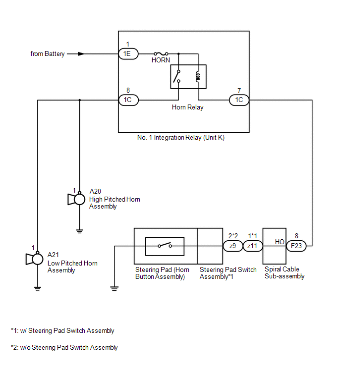
 Horn
Horn
Components
COMPONENTS
ILLUSTRATION
Inspection
INSPECTION
PROCEDURE
1. INSPECT HIGH PITCHED HORN ASSEMBLY
(a) Apply battery voltage and check the operation of the horn according to the
...
 Integration Relay
On-vehicle Inspection
ON-VEHICLE INSPECTION
PROCEDURE
1. REMOVE NO. 1 RELAY BLOCK COVER
(a) Remove the No. 1 relay block cover.
2. INSPECT NO. 1 INTEGRATION RELAY
(a) Using a screwd ...
Other materials about Toyota 4Runner:
General Maintenance
GENERAL MAINTENANCE
PROCEDURE
1. INSPECT STEERING LINKAGE AND GEAR HOUSING
(a) Check the steering wheel free play.
(b) Check the steering linkage for looseness or damage.
(1) Check that the tie rod ends do not have excessive play.
(2) Check that the dust ...
Prl Update
PRL UPDATE
1. PRL UPDATE
This function updates the PRL (Preferred Roaming List) of the DCM (Telematics
Transceiver). The PRL is a large set of phone numbers the DCM (Telematics Transceiver)
can utilize to make an emergency call when outside (roaming) the ...

0.0066