Toyota 4Runner: Integration Relay
On-vehicle Inspection
ON-VEHICLE INSPECTION
PROCEDURE
1. REMOVE NO. 1 RELAY BLOCK COVER
(a) Remove the No. 1 relay block cover.
2. INSPECT NO. 1 INTEGRATION RELAY
|
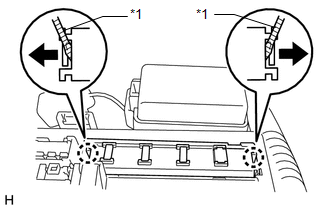
(a) Using a screwdriver, detach the 2 claws and disconnect the No. 1 integration relay from the engine room junction block. HINT: Tape the screwdriver tip before use. Text in Illustration
|
|
|
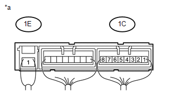
(b) Measure the resistance according to the value(s) in the table below. Standard Resistance:
If the result is not as specified, replace the No. 1 integration relay. Text in Illustration
|
|
(c) Attach the 2 claws to install the No. 1 integration relay to the engine room junction block.
3. INSTALL NO. 1 RELAY BLOCK COVER
(a) Install the No. 1 relay block cover.
 Horn System
Parts Location
PARTS LOCATION
ILLUSTRATION
Problem Symptoms Table
PROBLEM SYMPTOMS TABLE
HINT:
Use the table below to help determine the cause of problem symptoms. If multiple
suspected ...
 Lighting (ext)
...
Other materials about Toyota 4Runner:
Door Side Airbag Sensor RH Malfunction (B1690/15,B1695/16)
DESCRIPTION
The side airbag sensor LH or RH consists of the safing sensor, diagnostic circuit,
lateral deceleration sensor, etc.
If the center airbag sensor receives signals from the lateral deceleration sensor,
it determines whether the SRS should be ac ...
Inside rear view mirror
Glare from the headlights of vehicles behind can be reduced by using the
following functions:
Manual anti-glare inside rear view mirror
1. Normal position
2. Anti-glare position
Auto anti-glare inside rear view mirror
In automatic mode, sensors are u ...

0.0085