Toyota 4Runner: How To Proceed With Troubleshooting
CAUTION / NOTICE / HINT
IMPORTANT POINTS CONCERNING TROUBLESHOOTING
CAUTION:
Wait at least 90 seconds after disconnecting the cable from the negative (-) battery terminal to disable the SRS system.
NOTICE:
- Refer to the troubleshooting procedures of each system if DTCs regarding the CAN communication system are not output.
- Before measuring the resistance, leave the vehicle for at least 1 minute and do not operate the ignition switch, any switches or any doors. If doors need to be opened in order to check connectors, open the doors and leave them open.
- When disconnecting the cable, some systems need to be initialized after
the cable is reconnected (See page
.gif) ).
).
HINT:
- Operating the ignition switch, any switches or any doors triggers related ECU and sensor communication with the CAN, which causes resistance variation.
- *: Use the Techstream.
(a) DTCs indicating a CAN communication malfunction are also stored due to internal or power source-related problems in ECUs or sensors of systems using CAN communication. Therefore, check whether codes indicating internal or power source-related problems in those systems are output together with the CAN communication DTCs.
(b) It is possible to inspect the circuit of the DLC3 branch line or V1 bus main line for malfunctions by inspecting the terminals of the DLC3 using SST.
NOTICE:
It is only possible to inspect branch lines to ECUs (sensors) or the V1 bus from the DLC3.
(c) It is possible to check which ECUs (sensors) are not able to communicate via CAN communication by checking the "CAN Bus Check" function of the Techstream (when the DLC3 branch wire and V1 bus main wire are normal).
HINT:
- When checking "CAN Bus Check", ECUs (sensors) whose branch line is open or that cannot communicate via CAN communication do not respond to the Techstream (they are not displayed on the screen).
- When checking "CAN Bus Check", if a DTC indicating a CAN communication malfunction is output even though all ECUs (sensors) respond (they are displayed on the screen), use the DTC combination table to determine the suspected trouble area and perform symptom simulation.
(d) For past malfunctions of the V1 bus, the ECUs (sensors) which cannot communicate via CAN communication can be determined from the combination of CAN communication DTCs that are output.
(e) The power management control ECU detects malfunctions in the power management bus circuit and stores DTCs depending on the malfunctioning areas. The ECUs (sensors) which cannot communicate via CAN communication can be determined from the combination of CAN communication DTCs that are output.
(f) The main body ECU (multiplex network body ECU) detects malfunctions in the MS bus circuit and stores DTCs depending on the malfunctioning areas. The ECUs (sensors) which cannot communicate via CAN communication can be determined from the combination of CAN communication DTCs that are output.
(g) When an open circuit malfunction is confirmed, before disconnecting the connectors for inspection, check whether the connectors are loose by pushing in the connector case.
(h) When a connector is disconnected, check if the connector terminals or case is damaged, deformed, deteriorated, etc.
PROCEDURE
|
1. |
VEHICLE BROUGHT TO WORKSHOP |
|
.gif)
|
2. |
INSPECT BATTERY VOLTAGE |
Standard voltage:
11 to 14 V
If the voltage is below 11 V, recharge or replace the battery before proceeding.
|
|
3. |
CHECK AND CLEAR DTC* |
(a) Using the Techstream, perform the Health Check (all DTCs check).
NOTICE:
- If codes indicating internal or power source-related malfunctions of ECUs or sensors are output together with codes indicating that those ECUs or sensors cannot communicate via CAN communication, it is likely that the problem is not in the CAN communication line. Therefore, perform troubleshooting for the DTCs related to the malfunctioning parts first.
- If a connector of a system which includes a CAN communication line is disconnected when the ignition switch is ON or ACC, CAN communication DTCs are stored by that system and any related systems.
|
|
4. |
CHECK INSTALLED SYSTEMS (ECU AND SENSOR) THAT USE CAN COMMUNICATION |
(a) Based on the vehicle equipment and specifications, confirm the systems that
use CAN communication (See page ).
|
|
5. |
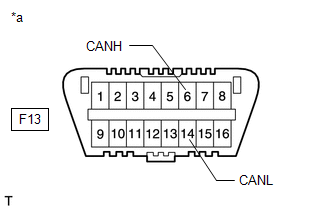
CHECK FOR OPEN CIRCUIT IN DLC3 BRANCH WIRE AND V1 BUS CIRCUIT MAIN WIRE AND SHORT CIRCUIT (CANH - CANL) |
(a) Disconnect the cable from the negative (-) battery terminal before measuring the resistances of the main wire and branch wire.
|
(b) Measure the resistance of the DLC3.
|
|
| B | .gif) |
GO TO "Open in CAN Main Wire" |
| C | |
GO TO "Short in CAN Bus Lines" |
|
|
6. |
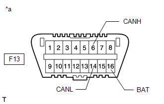
CHECK FOR SHORT TO +B IN CAN V1 BUS (CANH, CANL - BAT) |
|
(a) Measure the resistance of the DLC3. Standard Resistance:
|
|
| NG | |
GO TO "Short to B+ in CAN Bus Lines" |
|
|
7. |
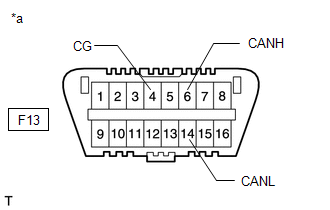
CHECK FOR SHORT TO GND IN CAN V1 BUS (CANH, CANL - CG) |
|
(a) Measure the resistance of the DLC3. Standard Resistance:
|
|
| NG | |
GO TO "Short to GND in CAN Bus Lines" |
|
|
8. |
CHECK ECUS CONNECTED TO CAN BUS* |
(a) Connect the cable to the negative (-) battery terminal.
NOTICE:
When disconnecting the cable, some systems need to be initialized after the cable
is reconnected (See page ).
(b) Select "CAN Bus Check" from the screen on the Techstream (See page
).
(c) Check the display of the connected ECUs and sensors for a minute.
|
Inspection Result |
Proceed to |
|---|---|
|
All ECUs and sensors connected to CAN communication system displayed on screen (CAN bus circuit currently normal) |
A |
|
w/ Smart Key System: Except for power management control ECU (Power Management1), no ECUs connected to power management bus are displayed (power management bus main wire open or short malfunction) |
B |
|
w/ Smart Key System: No ECUs connected to power management bus are displayed (the power management bus circuit is open) |
C |
|
w/ CRAWL Control: Except for main body ECU (multiplex network body ECU), no ECUs connected to MS bus are displayed (MS bus main wire open or short malfunction) |
D |
|
w/ Seat Position Memory: Except for main body ECU (multiplex network body ECU), no ECUs connected to MS bus are displayed (MS bus main wire open or short malfunction) |
E |
|
No ECUs connected to MS bus are displayed (branch wire between main body ECU (multiplex network body ECU) and MS bus circuit is open) |
F |
|
Only one ECU or sensor that should be connected to CAN communication is not displayed (ECU or sensor branch wire open or communication stop) |
G |
|
ECU or sensor that should be connected to CAN communication is not displayed or display is intermittent during check (ECU or sensor branch wire open on one side) |
H |
NOTICE:
ECUs and sensors that are not present are not displayed. Be careful not to mistake them for communication stop malfunctions.
HINT:
- If the display of an ECU is intermittent during the check, one side of an ECU or sensor branch wire is open (the signal of the ECU is treated as noise, which affects the response and display of the Techstream).
- w/ Smart Key System:
The power management control ECU checks for proper ECU communication for ECUs that are connected to the power management bus and the results are displayed on the Techstream. ECUs that stop communicating with the power management control ECU for 3 seconds or more stop being displayed on the Techstream.
The power management control ECU (Power Management1) may be malfunctioning if both of the following occur: 1) all ECUs connected to the power management bus are not displayed on the Techstream; and 2) DTC U1002 Lost Communication with Gateway Module (Power Management Bus) is not output.
- w/ CRAWL Control or w/ Seat Position Memory:
The main body ECU (multiplex network body ECU) checks for proper ECU communication for ECUs that are connected to the MS bus and the results are displayed on the Techstream. ECUs that stop communicating with the main body ECU (multiplex network body ECU) for 3 seconds or more stop being displayed on the Techstream.
The main body ECU (multiplex network body ECU) may be malfunctioning if both of the following occur: 1) all ECUs connected to the MS bus are not displayed on the Techstream; and 2) DTC U1002 Lost Communication with Gateway Module (MS Bus) is not output.
| B | |
GO TO "DTC U1002" |
| C | |
GO TO "Power Management Control ECU Communication Stop Mode" |
| D | |
GO TO "DTC U1002" |
| E | |
GO TO "DTC U1002" |
| F | |
GO TO "Main Body ECU Communication Stop Mode" |
| G | |
GO TO "PROBLEM SYMPTOMS TABLE" |
| H | |
GO TO "Open in One Side of CAN Branch Wire" |
|
|
9. |
CHECK COMMUNICATION MALFUNCTION DTC (PAST DTC CHECK)* |
(a) Select "CAN Bus Check" from the screen on the Techstream (See page
).
(b) Write down all of the DTCs output from each ECU.
HINT:
- If there are communication malfunction DTCs output but the Techstream "Bus Check - Communication Bus Check" screen displays all of the ECUs and sensors connected to the CAN system, the communication malfunction DTCs may be past malfunctions that are no longer present.
- For V1 bus main wire malfunctions, DTCs for related ECUs are also output. Therefore, determine the malfunctioning area based on all of the DTCs that are output.
- For MS bus malfunctions, DTCs are stored based on the detection of communication stop malfunctions and network malfunctions of ECUs that are connected by the main body ECU.
- For power management bus malfunctions, DTCs are stored based on the detection of communication stop malfunctions and network malfunctions of ECUs that are connected by the power management control ECU.
|
Inspection Result |
Proceed to |
|---|---|
|
ECU connected to V1 bus outputs communication trouble code |
A |
|
w/ Smart Key System: Power management control ECU (Power Management1) outputs network malfunction trouble code (U1002) (power management bus main wire past malfunction) |
B |
|
w/ Smart Key System: Power management control ECU (Power Management1) outputs trouble code other than network malfunction trouble code (U1002) (past malfunction of ECU or branch wire connected to power management bus) |
C |
|
w/ CRAWL Control: Main body ECU (multiplex network body ECU) outputs network malfunction trouble code (U1002) (MS bus main wire past malfunction) |
D |
|
w/ Seat Position Memory: Main body ECU (multiplex network body ECU) outputs network malfunction trouble code (U1002) (MS bus main wire past malfunction) |
E |
|
Main body ECU (multiplex network body ECU) outputs trouble code other than network malfunction trouble code (U1002) (past malfunction of ECU or branch wire connected to MS bus) |
F |
| B | |
GO TO "DTC U1002" |
| C | |
GO TO "DIAGNOSTIC TROUBLE CODE CHART" |
| D | |
GO TO "DTC U1002" |
| E | |
GO TO "DTC U1002" |
| F | |
GO TO "DIAGNOSTIC TROUBLE CODE CHART" |
|
|
10. |
CHECK DTC COMBINATION TABLE (V1 BUS BRANCH WIRE OPEN, PAST COMMUNICATION STOP MALFUNCTION) |
(a) Based on the combination of output CAN communication system DTCs, determine
which ECUs and sensors have a communication stop malfunction (See page
).
|
|
11. |
PERFORM MALFUNCTION SIMULATION TEST (V1 BUS CIRCUIT MAIN WIRE PAST MALFUNCTION)* |
(a) Using the Techstream, clear all DTCs.
(b) Perform a malfunction simulation test on all harnesses and connectors related to the V1 bus main wire.
(c) Check the DTCs that were output as a result of the malfunction simulation test. Then determine the malfunctioning area.
|
|
12. |
ADJUST, REPAIR AND REPLACE |
|
|
13. |
CLEAR DTC* |
(a) Using the Techstream, clear all DTCs.
|
|
14. |
CONFIRMATION TEST |
| NEXT | |
END |
 System Diagram
SYSTEM DIAGRAM
w/ Smart Key System
No.
ECU/Sensor Name
1
Combination meter assembly
2
Skid control ECU (master cylinder ...
 Problem Symptoms Table
PROBLEM SYMPTOMS TABLE
HINT:
Use the table below to help determine the cause of problem symptoms. If multiple
suspected areas are listed, the potential causes of the symptoms are listed in order
...
Other materials about Toyota 4Runner:
Pressure Control Solenoid "B" Performance (Shift Solenoid Valve SL2) (P0776)
DESCRIPTION
The ECM uses signals from the output shaft speed sensor and input speed sensor
to detect the actual gear position (1st, 2nd, 3rd, 4th or 5th gear).
Then the ECM compares the actual gear with the shift schedule in the ECM memory
to detect mech ...
Switching the display
Items displayed can be switched by pressing the display change button.
Odometer
Displays the total distance the vehicle has been driven.
Trip meter
Displays the distance the vehicle has been driven since the meter was last
reset. Trip meters “A” ...

0.0066