Toyota 4Runner: ID Code Box Power Source Circuit
DESCRIPTION
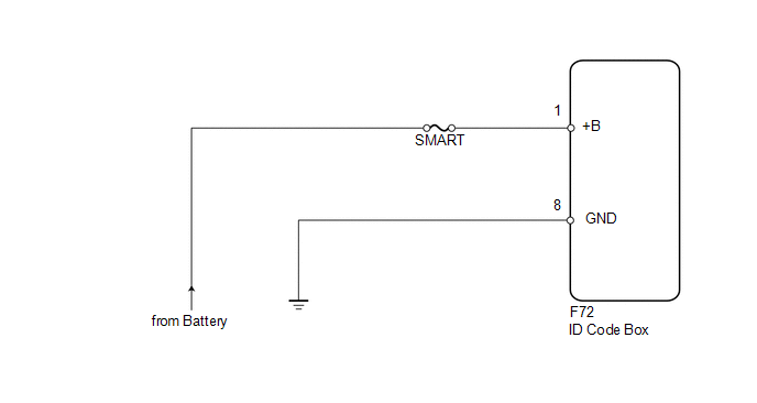
This circuit provides power to operate the ID code box.
WIRING DIAGRAM
CAUTION / NOTICE / HINT
NOTICE:
Inspect the fuses for circuits related to this system before performing the following inspection procedure.
PROCEDURE
|
1. |
CHECK HARNESS AND CONNECTOR (ID CODE BOX - BATTERY AND BODY GROUND) |
|
(a) Disconnect the F72 box connector. |
|
.png)
(b) Measure the voltage according to the value(s) in the table below.
Standard Voltage:
|
Tester Connection |
Condition |
Specified Condition |
|---|---|---|
|
F72-1 (+B) - Body ground |
Always |
11 to 14 V |
(c) Measure the resistance according to the value(s) in the table below.
Standard Resistance:
|
Tester Connection |
Condition |
Specified Condition |
|---|---|---|
|
F72-8 (GND) - Body ground |
Always |
Below 1 Ω |
|
*a |
Front view of wire harness connector (to ID Code Box) |
| OK | .gif) |
PROCEED TO NEXT SUSPECTED AREA SHOWN IN PROBLEM SYMPTOMS TABLE |
| NG | |
REPAIR OR REPLACE HARNESS OR CONNECTOR |
 Certification ECU Power Source Circuit
DESCRIPTION
This circuit provides power to the certification ECU.
WIRING DIAGRAM
CAUTION / NOTICE / HINT
NOTICE:
Inspect the fuses for circuits related to this system before performing the foll ...
 Security Indicator Light Circuit
DESCRIPTION
When the engine immobiliser system is set, the security indicator flashes
continuously, but does not illuminate if the engine immobiliser system is
not set.
WIRING D ...
Other materials about Toyota 4Runner:
ECU Initial Setting Incomplete (C120A)
DESCRIPTION
w/ Downhill Assist Control or w/ Crawl Control:
When the master cylinder solenoid (skid control ECU) is replaced, the master
cylinder solenoid (skid control ECU) must be informed that the vehicle is equipped
with downhill assist control and/o ...
Front Vertical Sensor Malfunction (B2652)
DESCRIPTION
When the front power seat switch LH does not receive a sensor signal despite
upward or downward movement of the front of the seat cushion by power seat motor
operation, this DTC is stored.
DTC Code
DTC Detection Conditio ...

0.0261