Toyota 4Runner: Security Indicator Light Circuit
DESCRIPTION
- When the engine immobiliser system is set, the security indicator flashes continuously, but does not illuminate if the engine immobiliser system is not set.
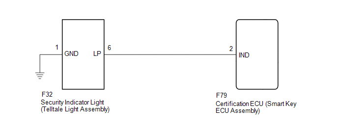
WIRING DIAGRAM
CAUTION / NOTICE / HINT
NOTICE:
Before replacing the certification ECU (smart key ECU assembly), refer to Registration
(See page .gif) ).
).
PROCEDURE
|
1. |
PERFORM ACTIVE TEST USING TECHSTREAM (IMMOBILISER INDICATOR) |
(a) Check that the security indicator light illuminates when operating it with
the Active Test (See page ).
Smart Key
|
Tester Display |
Test Part |
Control Range |
Diagnostic Note |
|---|---|---|---|
|
Immobiliser Indicator |
Security indicator light |
ON/OFF |
The test is possible when the following conditions are met:
|
OK:
Security indicator light can be turned on and off using the Techstream.
| OK | .gif) |
PROCEED TO NEXT SUSPECTED AREA SHOWN IN PROBLEM SYMPTOMS TABLE |
|
.gif)
|
2. |
INSPECT SECURITY INDICATOR LIGHT (TELLTALE LIGHT ASSEMBLY) |
(a) Remove the security indicator light (telltale light assembly) (See page
).
(b) Inspect the security indicator light (telltale light assembly) (See page
).
| NG | |
REPLACE SECURITY INDICATOR LIGHT (TELLTALE LIGHT ASSEMBLY) |
|
|
3. |
CHECK HARNESS AND CONNECTOR (TELLTALE LIGHT ASSEMBLY - CERTIFICATION ECU AND BODY GROUND) |
(a) Disconnect the F32 security indicator light (telltale light assembly) connector.
(b) Disconnect the F79 certification ECU (smart key ECU assembly) connector.
(c) Measure the resistance according to the value(s) in the table below.
Standard Resistance:
|
Tester Connection |
Condition |
Specified Condition |
|---|---|---|
|
F32-6 (LP) - F79-2 (IND) |
Always |
Below 1 Ω |
|
F32-1 (GND) - Body ground |
Always |
Below 1 Ω |
|
F32-6 (LP) or F79-2 (IND) - Body ground |
Always |
10 kΩ or higher |
| OK | |
REPLACE CERTIFICATION ECU (SMART KEY ECU ASSEMBLY) |
| NG | |
REPAIR OR REPLACE HARNESS OR CONNECTOR |
 ID Code Box Power Source Circuit
DESCRIPTION
This circuit provides power to operate the ID code box.
WIRING DIAGRAM
CAUTION / NOTICE / HINT
NOTICE:
Inspect the fuses for circuits related to this system before performing the fo ...

Other materials about Toyota 4Runner:
Engine Immobiliser System Malfunction (B2799)
DESCRIPTION
This DTC is stored when one of the following occurs: 1) the ECM detects errors
in its own communications with the transponder key ECU assembly; 2) the ECM detects
errors in the communication lines; or 3) the ECU - ECM communication ID between ...
Removal
REMOVAL
PROCEDURE
1. DISCONNECT CABLE FROM NEGATIVE BATTERY TERMINAL
CAUTION:
Wait at least 90 seconds after disconnecting the cable from the negative (-)
battery terminal to disable the SRS system.
NOTICE:
When disconnecting the cable, some systems ne ...

0.0249