Toyota 4Runner: IG2 Signal Malfunction (B2788)
DESCRIPTION
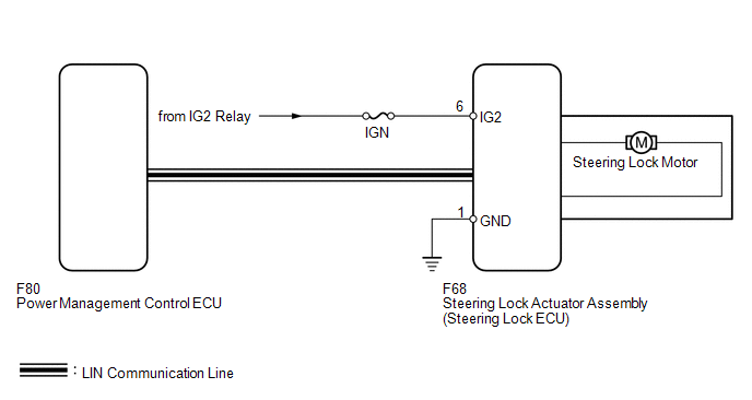
The steering lock ECU determines the on/off status of the engine switch through the IG2 signal circuit.
The steering lock ECU does not lock the steering when it receives the IG2 relay on signal. This prevents the steering from being locked while the vehicle is moving.
The diagnosis information of the steering lock ECU is transmitted to the Techstream via the certification ECU as the steering lock ECU is not connected to the CAN communication system.
|
DTC Code |
Detection Condition |
Trouble Area |
|---|---|---|
|
B2788 |
The IG2 input to the steering lock ECU does not match the LIN communication input. |
|
WIRING DIAGRAM
CAUTION / NOTICE / HINT
HINT:
When the engine switch is off, the main body ECU may occasionally go into a non-active state called sleep mode. Therefore, before proceeding with the inspection, it is necessary to perform the following steps to wake up the ECU:
With the engine switch off, open the driver door. Then (with the engine switch still off) open and close any door several times at 1.5 second intervals.
NOTICE:
- If the steering lock actuator assembly (steering lock ECU) is replaced, with the engine switch off and the shift lever in P, open and close the driver side door to record the current lock position into the steering lock ECU. If this is not performed, the engine may not start.
- When replacing the steering lock ECU, registration must be performed
(See page
.gif) ).
). - Inspect the fuses for circuits related to this system before performing the following inspection procedure.
PROCEDURE
|
1. |
CHECK STEERING LOCK ACTUATOR ASSEMBLY (STEERING LOCK ECU) |
|
(a) Disconnect the F68 steering lock ECU connector. |
|
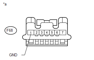
(b) Measure the resistance according to the value(s) in the table below.
Standard Resistance:
|
Tester Connection |
Condition |
Specified Condition |
|---|---|---|
|
F68-1 (GND) - Body ground |
Always |
Below 1 Ω |
|
*a |
Front view of wire harness connector (to Steering Lock ECU) |
|
(c) Reconnect the F68 steering lock ECU connector. |
|
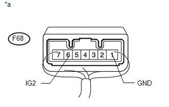
(d) Measure the voltage according to the value(s) in the table below.
Standard Voltage:
|
Tester Connection |
Switch Condition |
Specified Condition |
|---|---|---|
|
F68-6 (IG2) - F68-1 (GND) |
Engine switch on (IG) |
11 to 14 V |
|
F68-6 (IG2) - F68-1 (GND) |
Engine switch off |
Below 1 V |
|
*a |
Component with harness connected (Steering Lock ECU) |
| OK | .gif) |
REPLACE STEERING LOCK ACTUATOR ASSEMBLY (STEERING LOCK ECU) |
| NG | |
CHECK FOR SHORT IN ALL HARNESSES, CONNECTORS AND COMPONENTS CONNECTED TO IG2 FUSE |
 Diagnostic Trouble Code Chart
DIAGNOSTIC TROUBLE CODE CHART
HINT:
If a trouble code is output during the DTC check, inspect the trouble areas listed
for that code. For details of the code, refer to the "See page" bel ...
 Power Source Control ECU Malfunction (B2782)
DESCRIPTION
The steering lock ECU activates the steering lock motor with the power from the
power management control ECU through the IGE circuit. This prevents the steering
from being locked whil ...
Other materials about Toyota 4Runner:
Terminals Of Ecu
TERMINALS OF ECU
1. CHECK DRIVER SIDE JUNCTION BLOCK ASSEMBLY, MAIN BODY ECU (MULTIPLEX NETWORK
BODY ECU)
(a) Remove the main body ECU (multiplex network body ECU) (See page
).
(b) Measure the voltage and resistance according to the value(s) in the ta ...
Inside Vehicle
General Maintenance
GENERAL MAINTENANCE
CAUTION / NOTICE / HINT
Performing the following maintenance checks on the vehicle is the owner's responsibility.
The owner may perform the maintenance or take the vehicle to a service center. Check
the part ...

0.0068